Next up we’ll start putting together the suspension arms
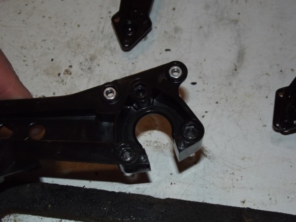
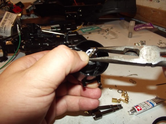
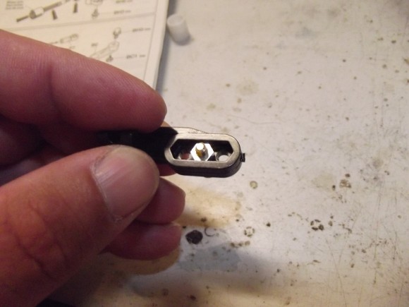
Just like in the other instances where we were using a screw and nut, there are hex shaped holes on one side to hold the nuts in place.
In this case, they are for ball studs
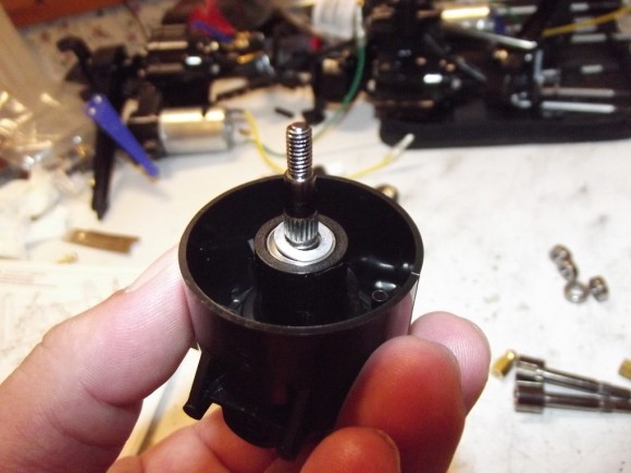
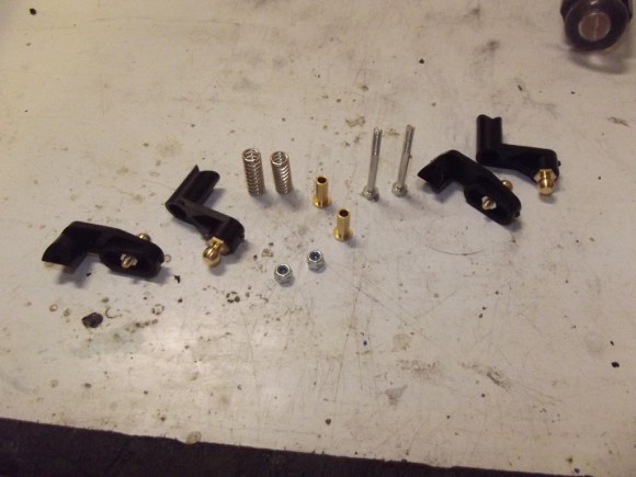
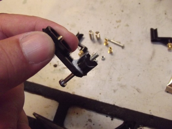
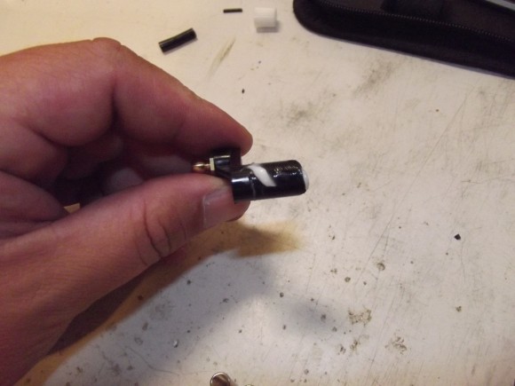
The suspension arms will be assembled to form the socket portion of this ball and socket setup.
This is the ball the suspension arms surround. That cavity will get a little grease to keep things moving freely.
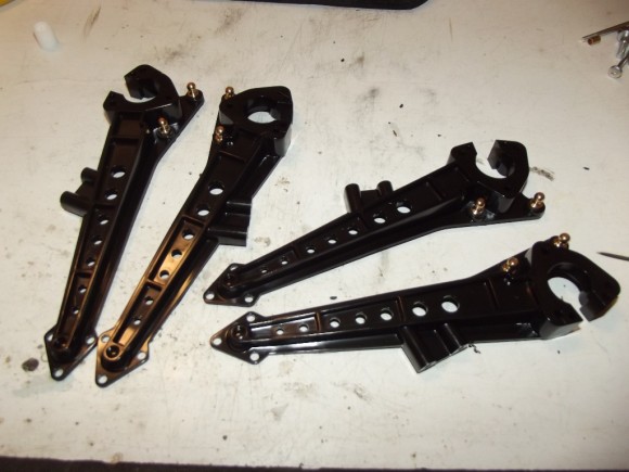
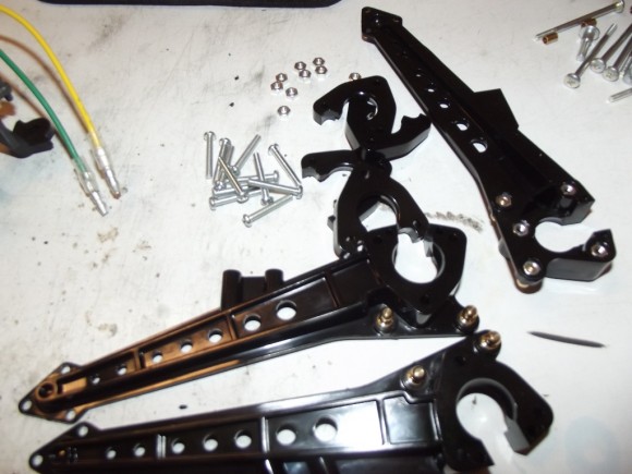
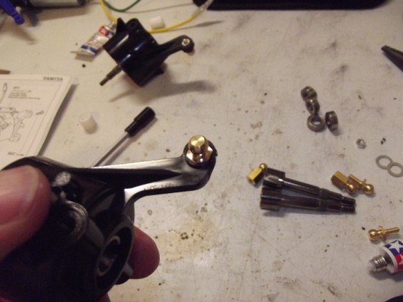
The suspension arms go on the inside of the ball, with the outside piece being screwed in to form a socket around the ball
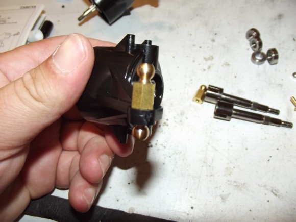
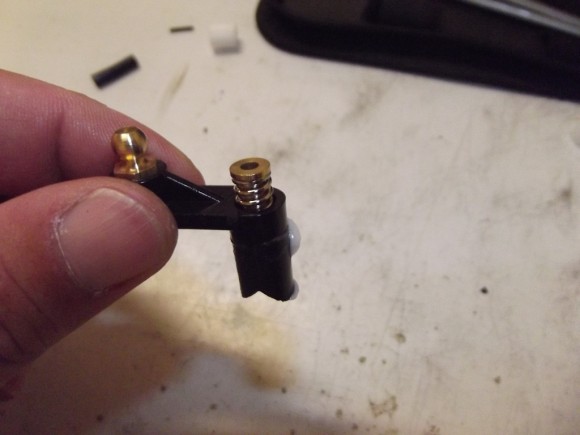
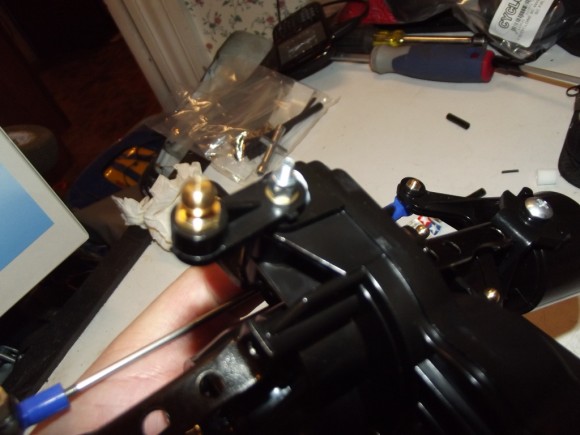
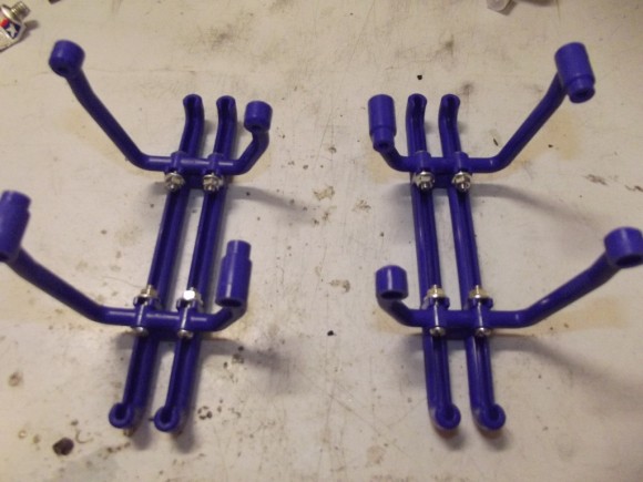
Notice the arms are not interchangeable. You must put the correct ones on so that the ball studs face outward. These will be used as lower shock mounts later on in the build.
Make sure you throw a little grease in there to keep things moving freely.
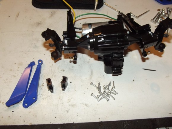
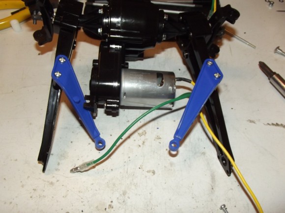
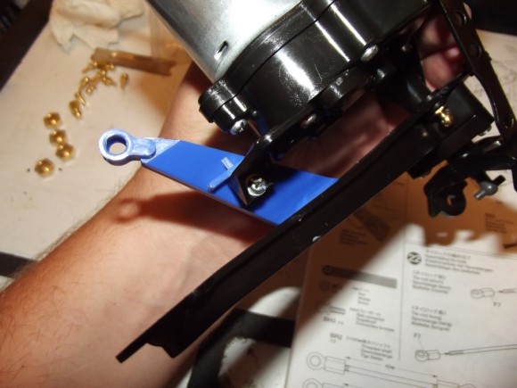
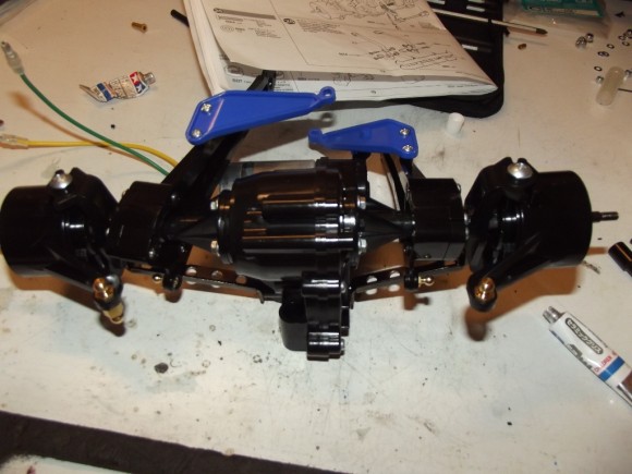
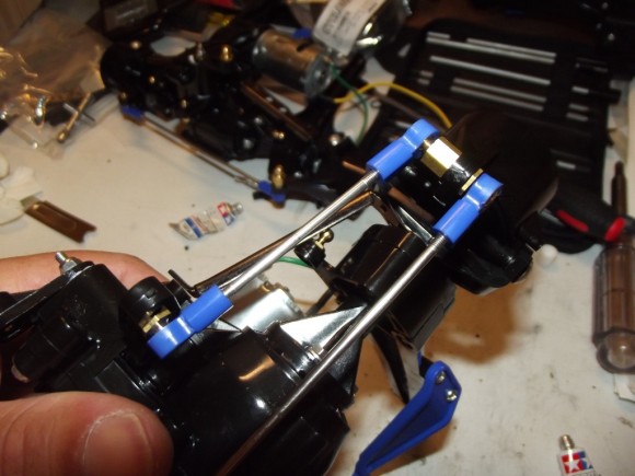
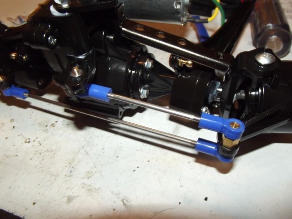
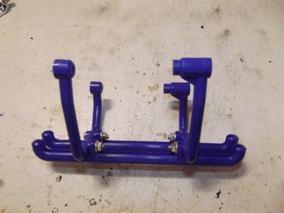
These blue arms are for lateral support
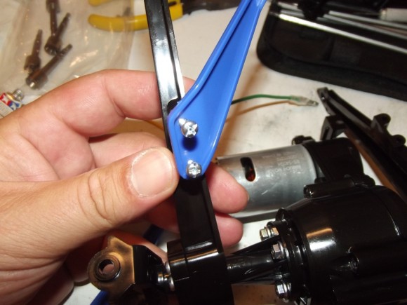
First we’ll attach them to the suspension arms
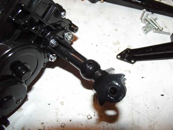
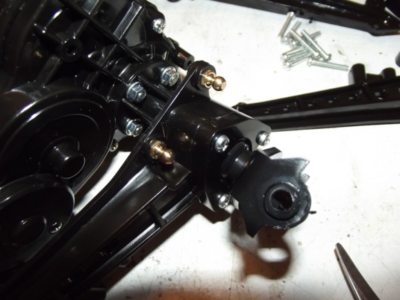
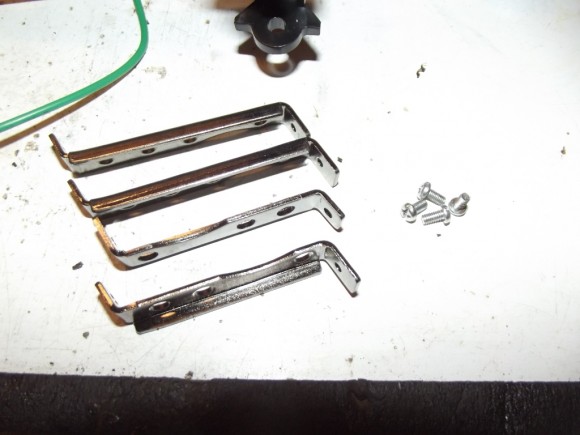
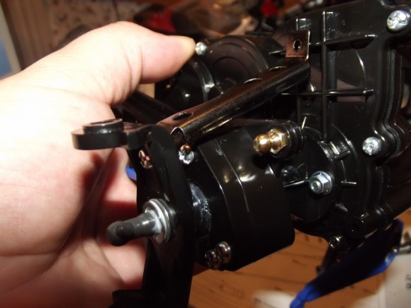
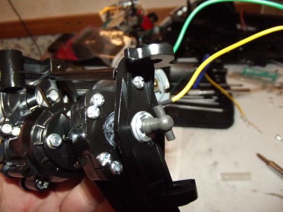
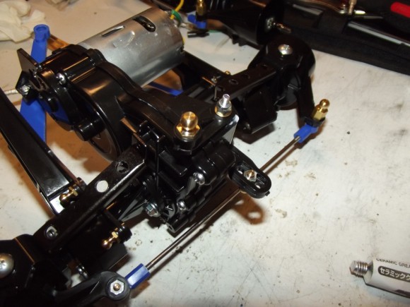
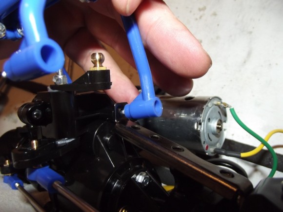
These are axle stays. They will be used as support from the axle tubes to the gear cases.
There are two different length brackets, but it is easy to see which goes where.
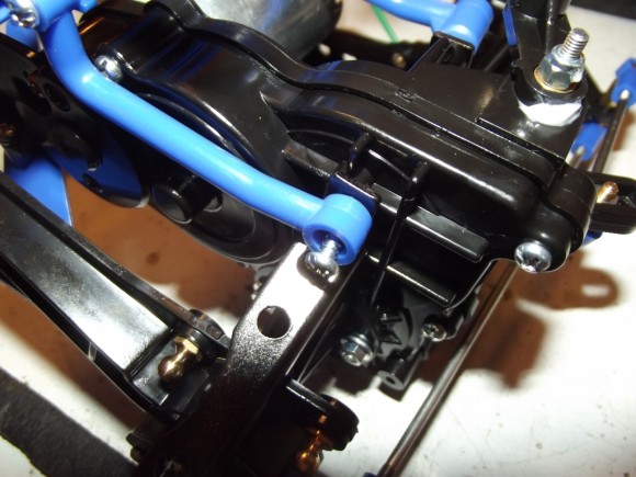
This is the mount from earlier, where we installed the plastic insert to leave a recess next to the motor. Just more support for the heavy gear cases.
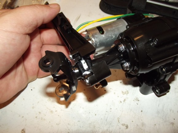
On the outside, the axle stay gets a screw through the rather large C Hub
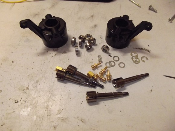
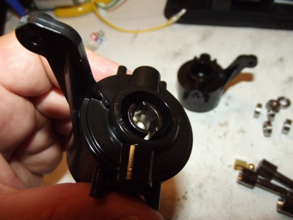
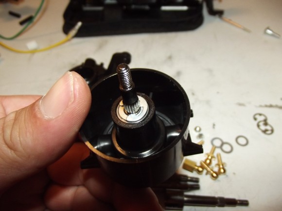
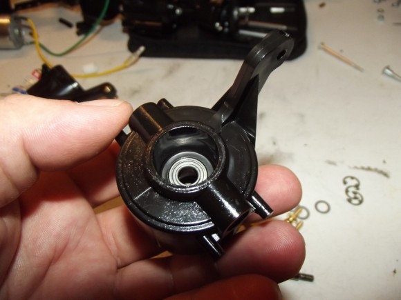
With the stock setup, the Clodbuster has 4 wheel steering. This was done to make the truck more realistic, as well as to give it a tighter turning radius. As such, there are 4 steering knuckles. One for each corner.
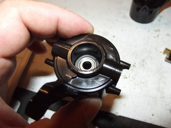
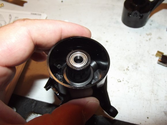
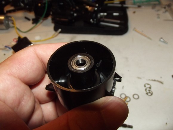
They each get bearings on both sides.
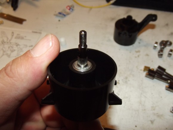
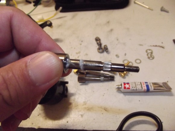
The wheel axle gets inserted, with a little bit of grease for good measure. It is probably less needed in this instance, because we are using top of the line bearings vs stock.
On the inside, throw a washer on the wheel axle
Before holding it place with an E Clip
Here we’ll prep the opposite side
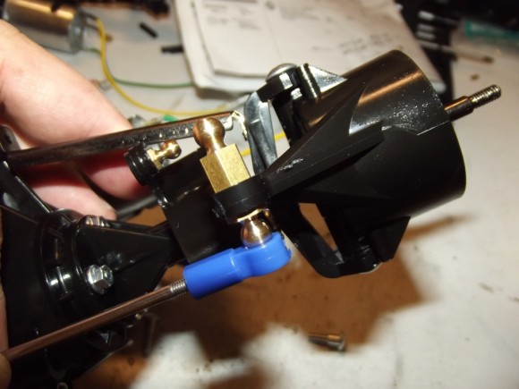
On one of the steering knuckles, you will thread two ball studs into each other. This is so that the link that goes from knuckle to knuckle can go on the bottom, and the link from the servo saver can go on top. The opposite side just gets the one ball stud for the wheel to wheel link.
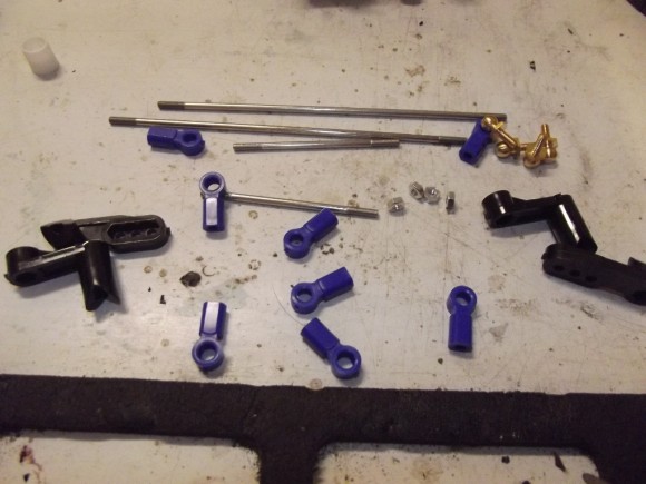
The rest of the steering linkage
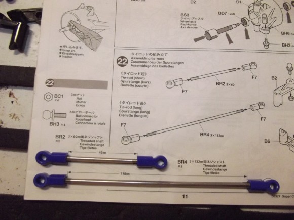
Just like before, there is a scale picture of the steering links so you can prebuild them to the appropriate length.
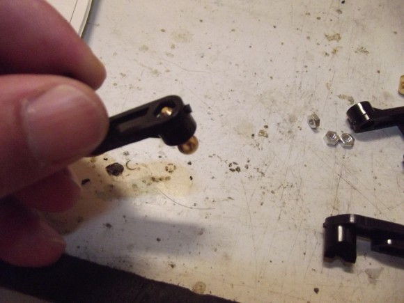
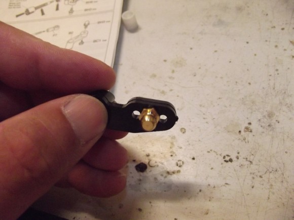
These are the pieces that will form the servo saver, the ball stud gets installed with a nut on the underside
There are three mounting positions on this arm, in order to adjust throw. I put it in the middle hole to start with
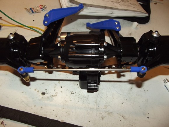
The longer link will connect the two steering knuckles to each other
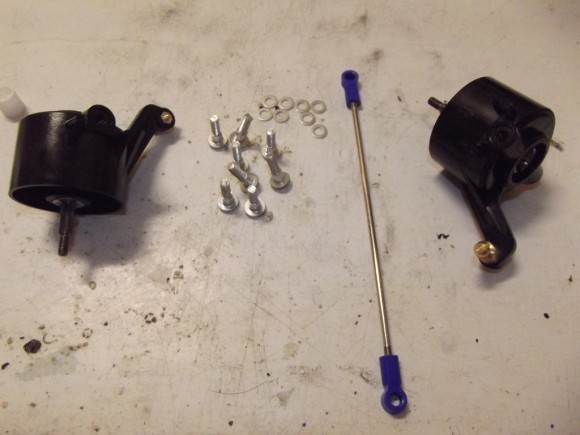
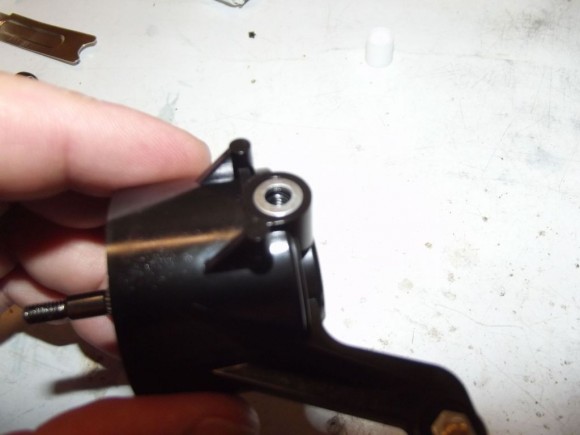
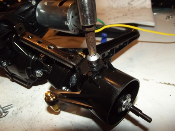
Preparing to mount the steering knuckles to the C Hubs. This washer will help prevent binding.
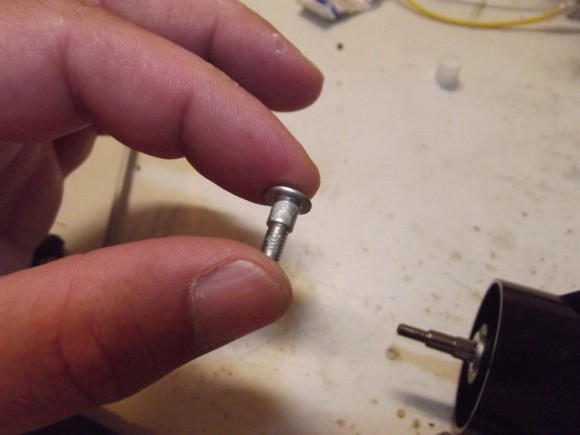
The steering knuckles are held in place with shoulder screws, throw a dab of grease on there to help it rotate freely.
There are two shoulder screws per hub, one for the top and bottom respectively
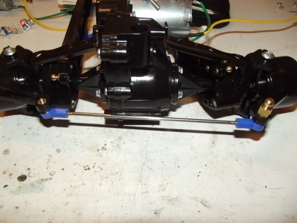
Once attached it should look something like this.
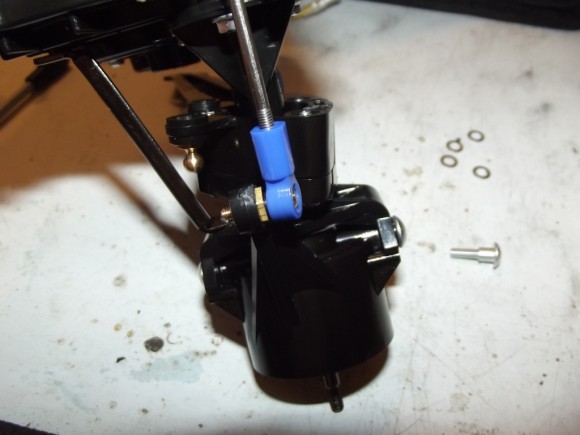
The long steering link connects the two steering knuckles together, and pops onto the ball studs on the underside of the arm.
Now we can repeat for the oppostie gear case. Since this truck has 4 wheel steering everything is the same.
It is time to assemble the servo savers.
This is the first time you will vary from the front to the rear gearbox. Depending on which one you mount to first, the servo saver arms face opposite directions. Make sure you grease these so they operate freely.
The assembly is spring loaded so you can adjust the tension
In both the front and rear gear cases, the servo saver arm has to face the driver’s side of the truck
From the bottom of the servo saver, attach the short steering link to the steering knuckle with the ball stud on top.
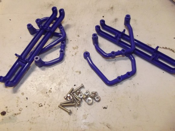
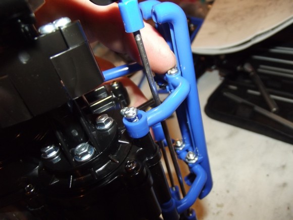
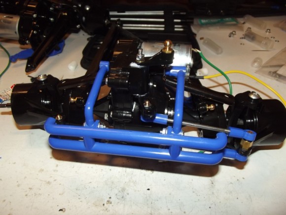
The gear cases get these fancy cages for protection
They go together simple enough
The top mount is screwed through the top screw for the axle stay bracket
And the bottom is screwed directly into the gear case.
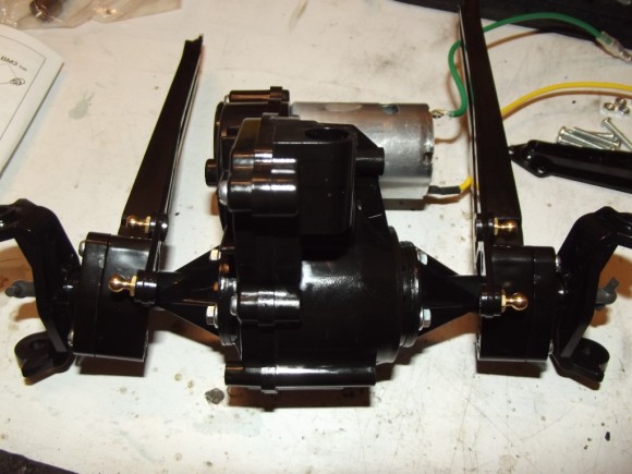
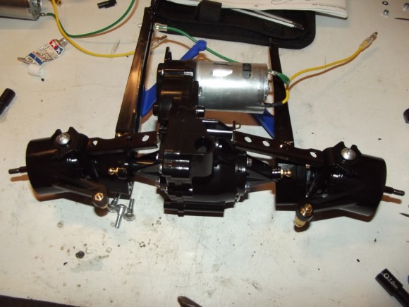
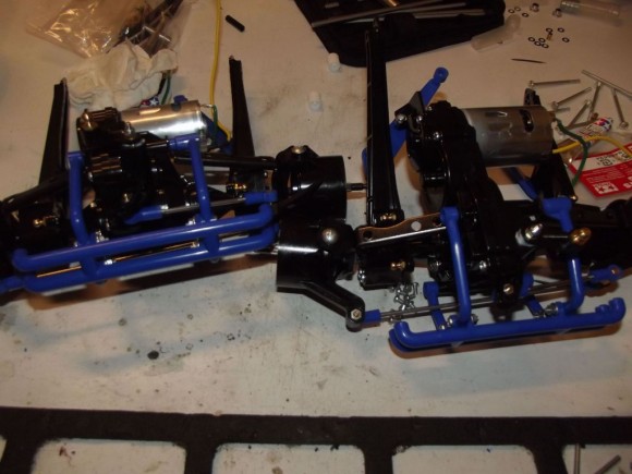
Here we go, both gear cases completely assembled, ready to be mounted to the chassis.


 August 20th, 2012
  Matt
Matt 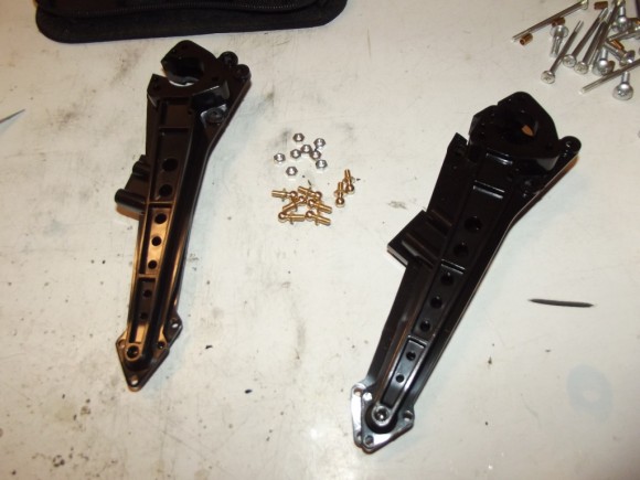
 Posted in
  Tags:
Tags:
[…] RCSoup.com Tamiya Clodbuster Build Check this out guys Tamiya Super Clodbuster – Build up | RC Soup […]