

 June 4th, 2013
  Jarodd
 Bag C is the start of the front and rear suspension assemblies.
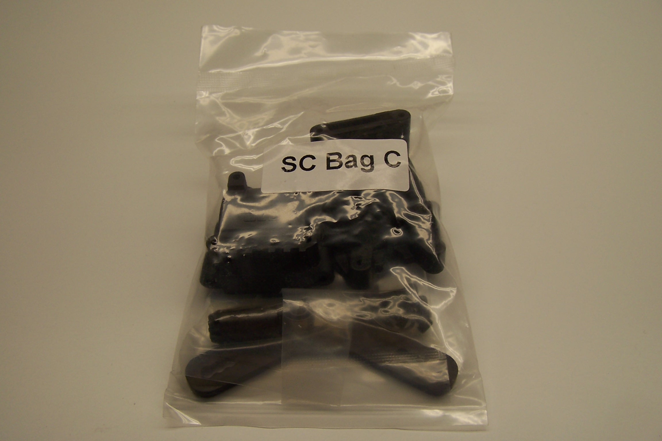 Once again all of the screws are contained in the bags.
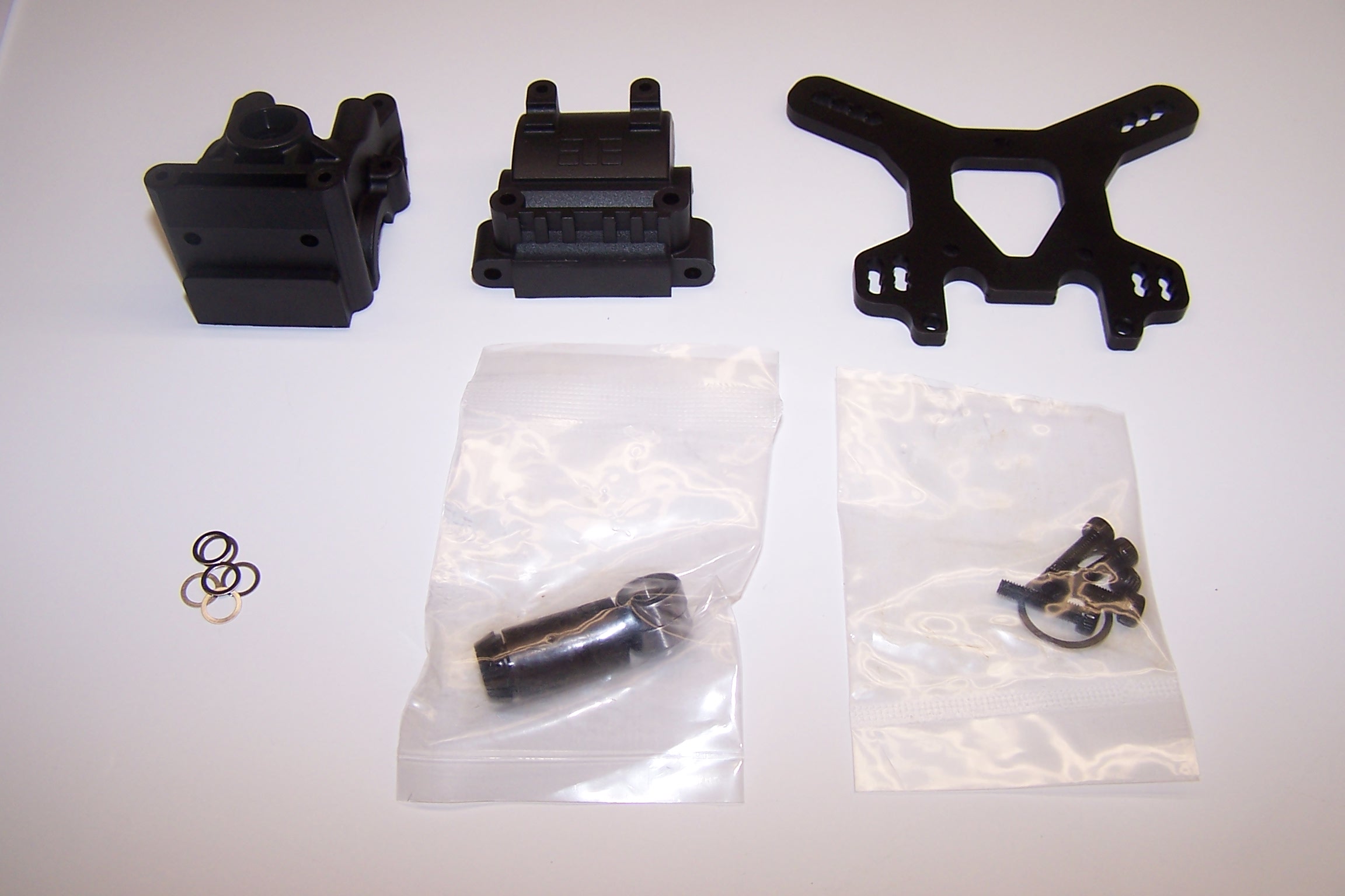
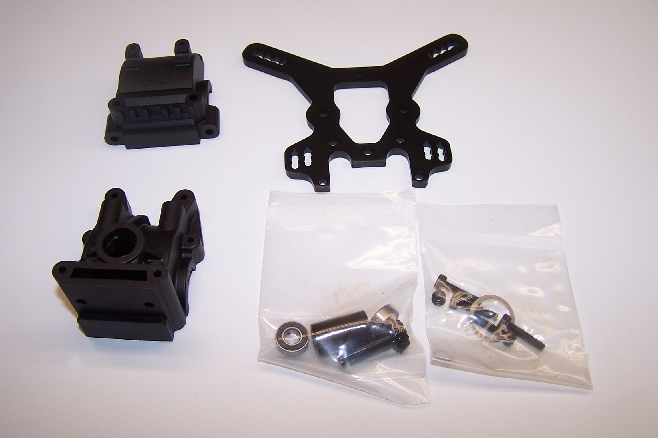
The housing are from high quality molds and did not contain flashing that had to be cut away to fit. The shock tower is very thick (4mm 7075 aluminum) and appears to be bulletproof (probably won’t test that theory with my 12 gauge though).
Only one shim was needed on one side to get the proper mesh.
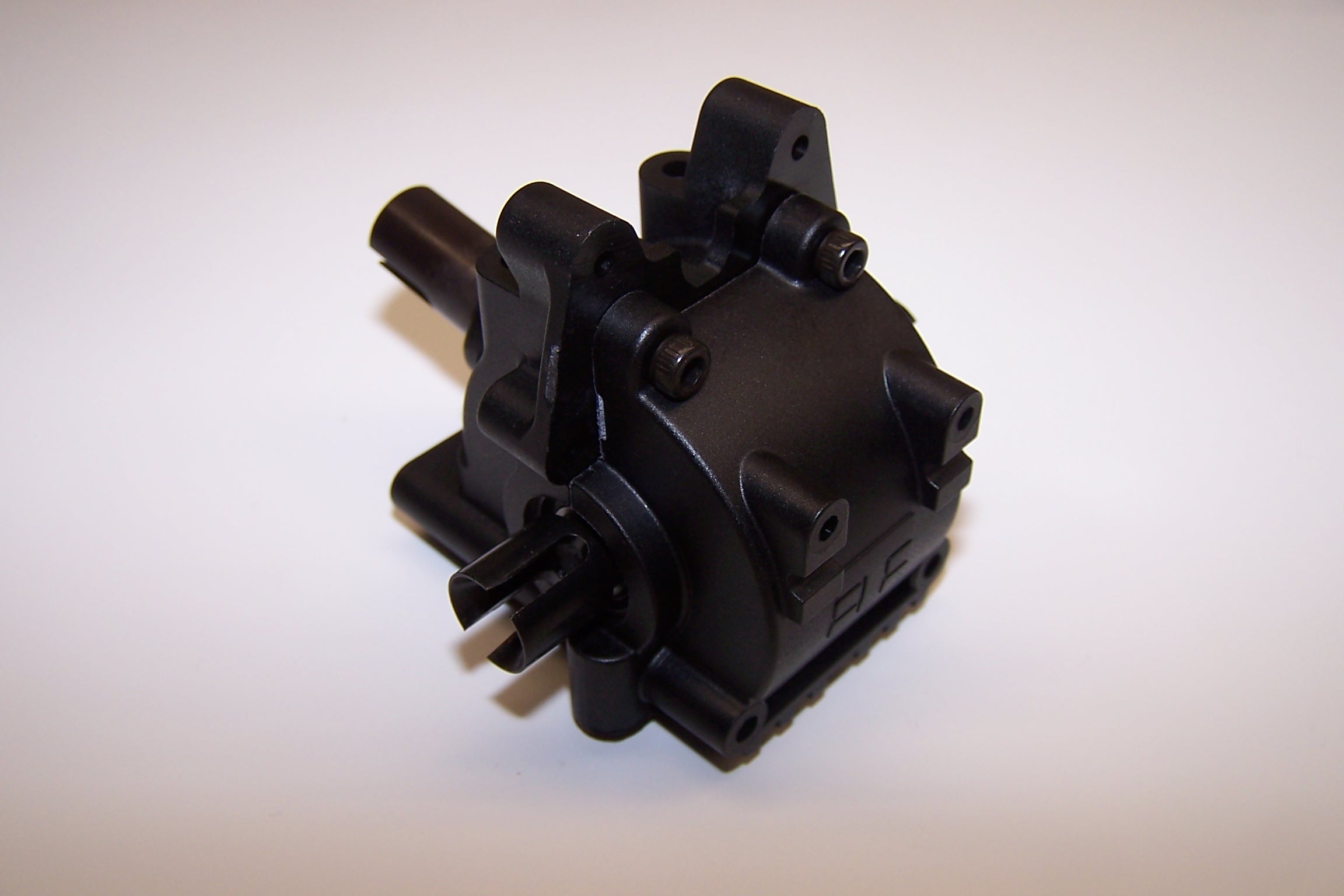
The rear assembly goes together the same as the front. The shock towers are a tight fit around the housing which makes the assembly strong.
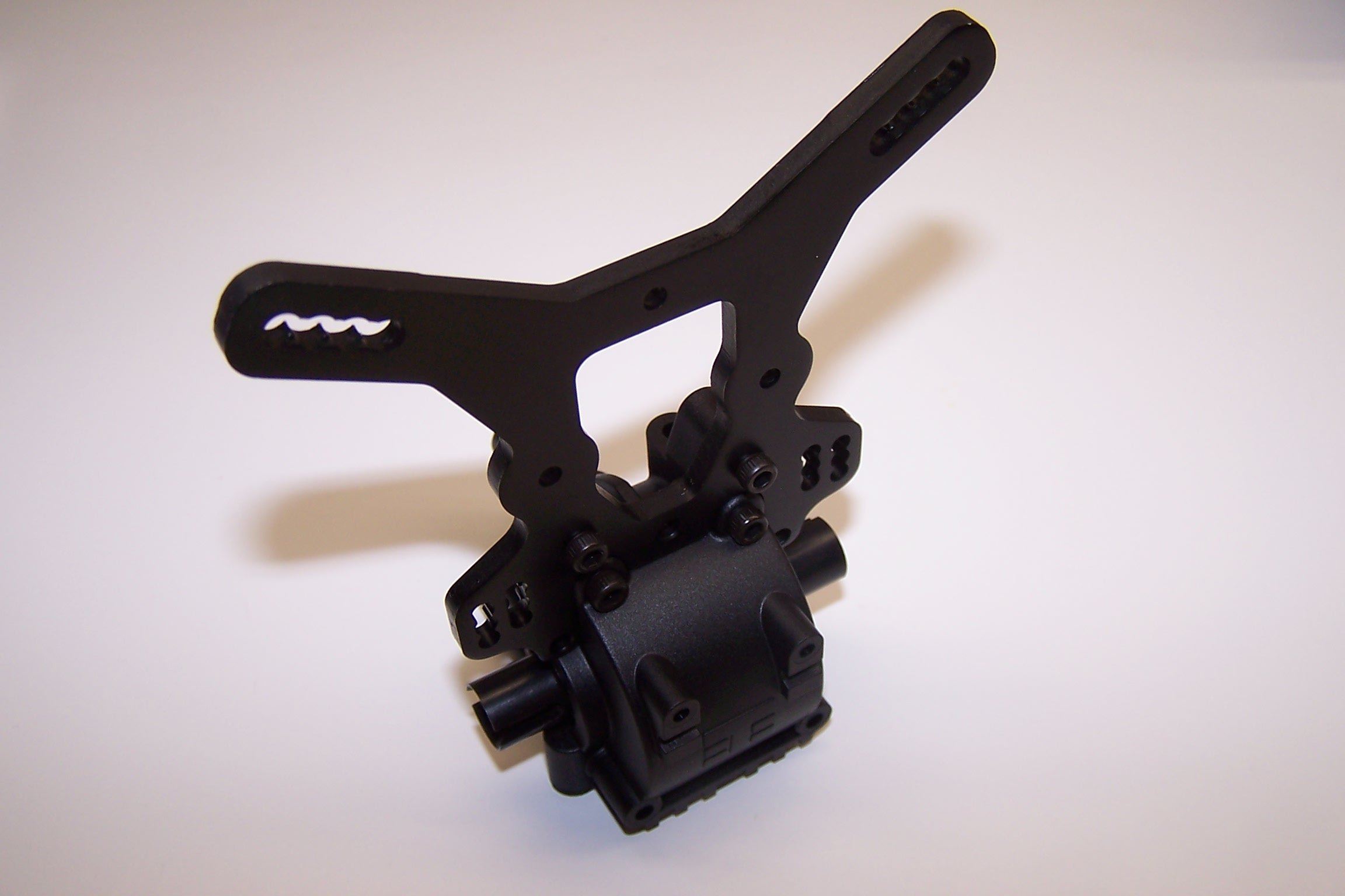
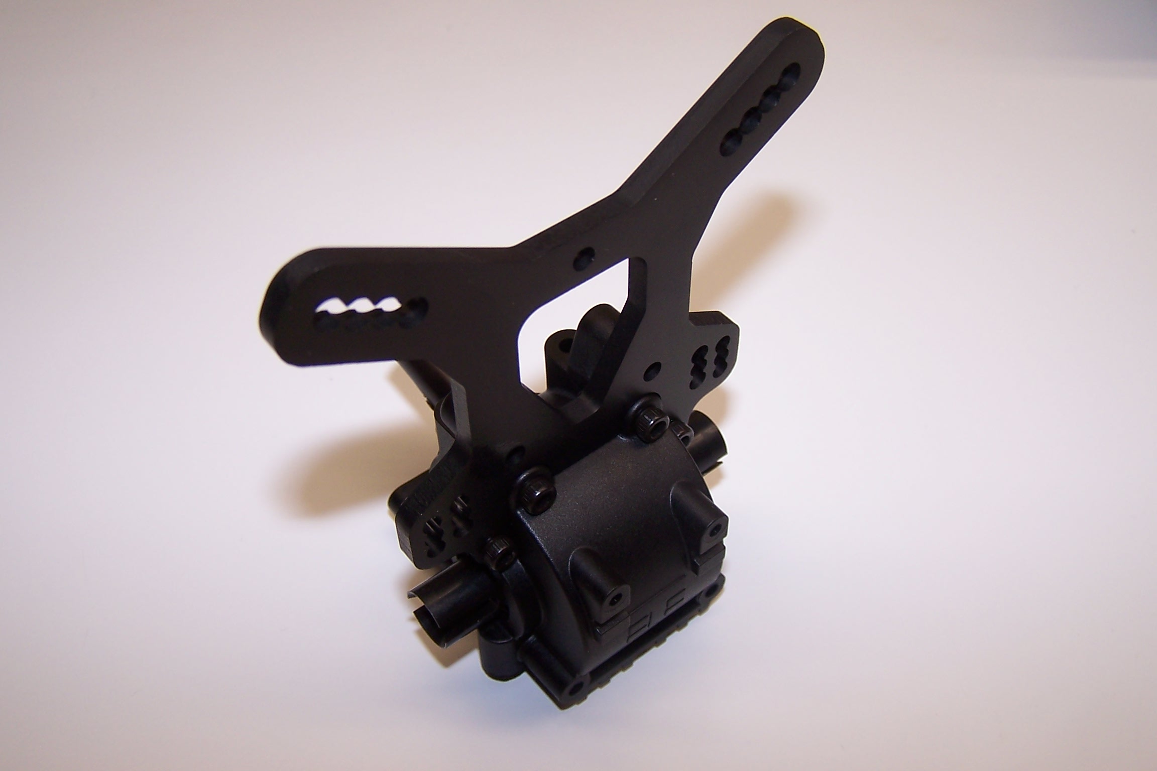
Completed unit with shock tower.
Bag E includes the rear arms, rear bumper, sway bar, and hinge pin holders.
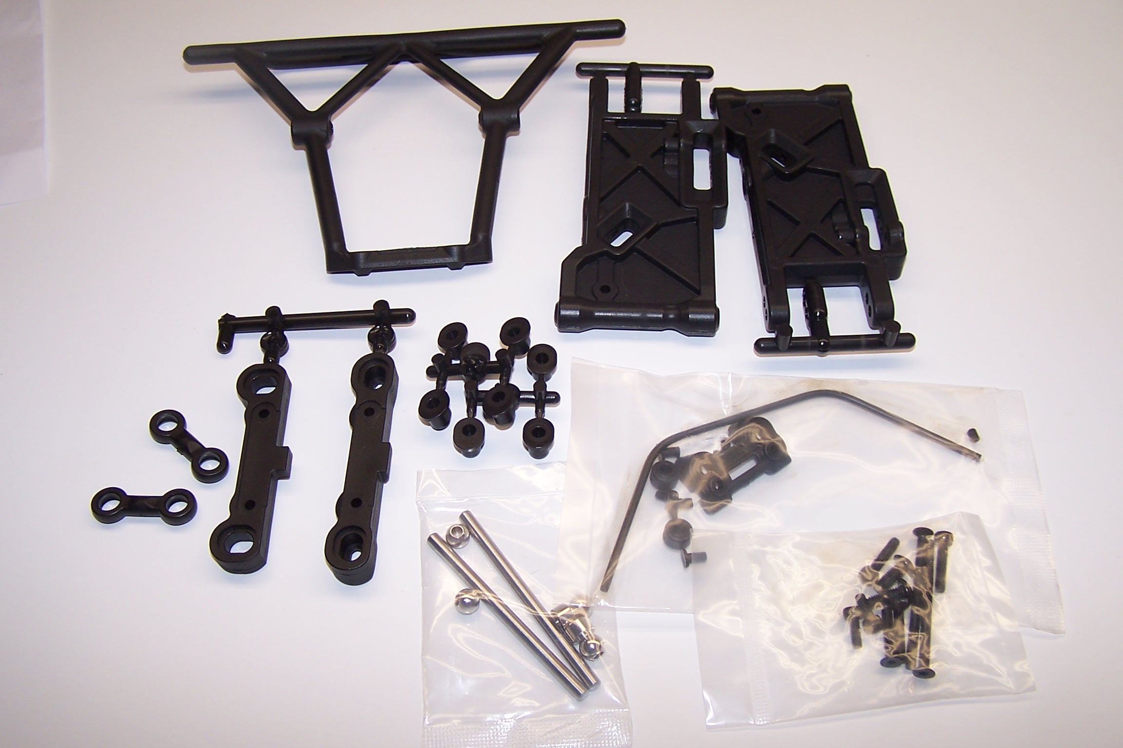
The kit includes the optional parts to change anti-squat and toe-in. The arms are also symmetrical which means you can use them on either side. This is handy if you break one because you always have spares.
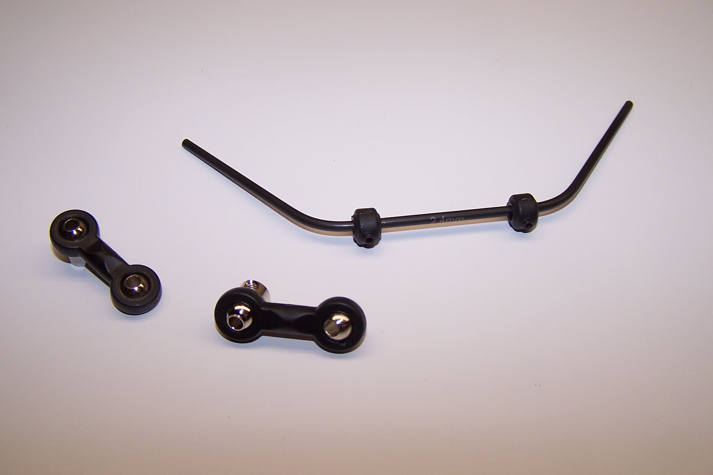
The 2.4 mm sway bars come standard, but Tekno R/C offers other diameters to suit your track conditions.
The sway bars are attached with only a slight resistance to them. No binding.
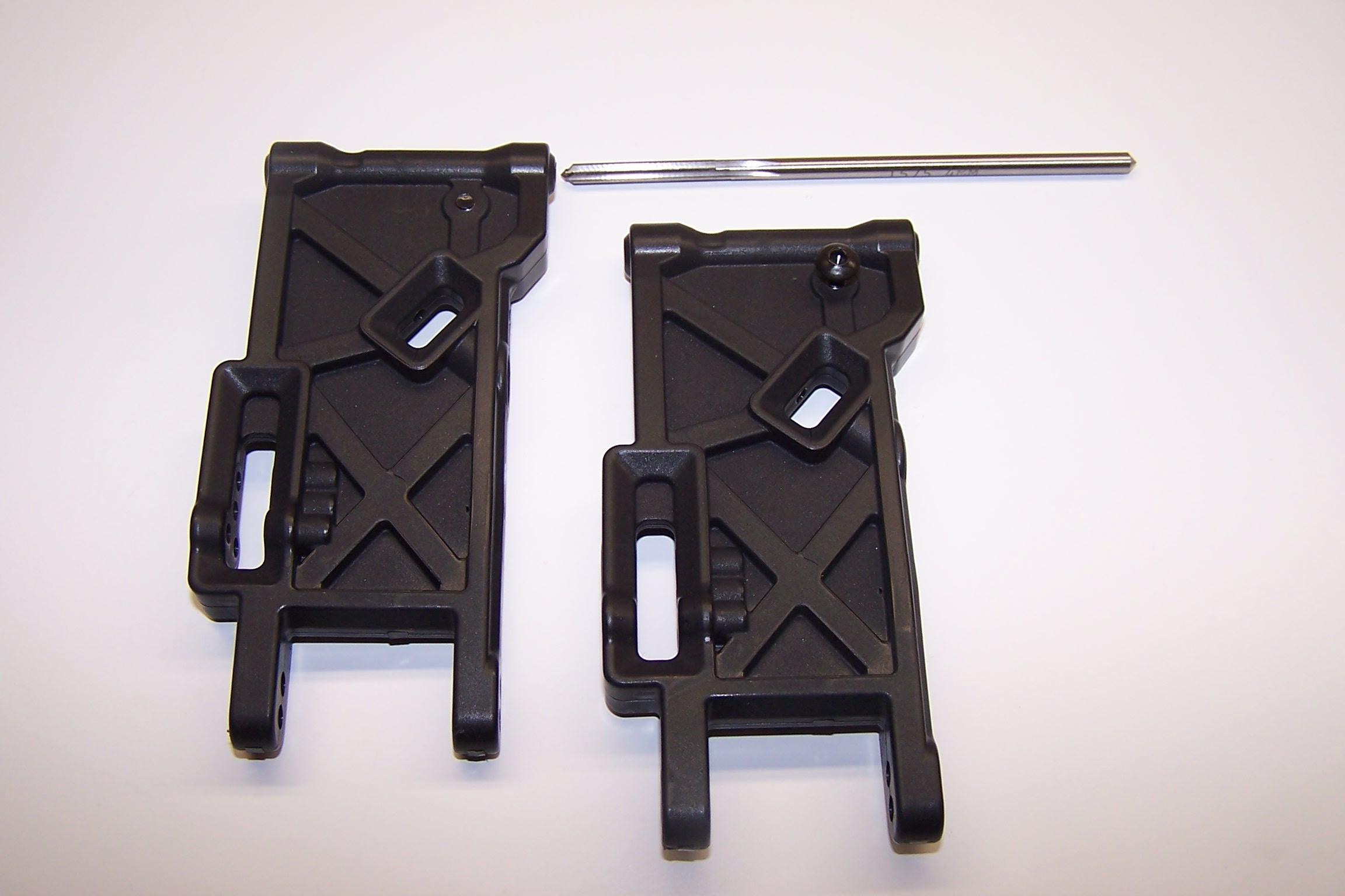
To make sure the hinge pin holes were perfectly straight I ran a 4mm reamer through them. Only a slight amount of flashing was removed.
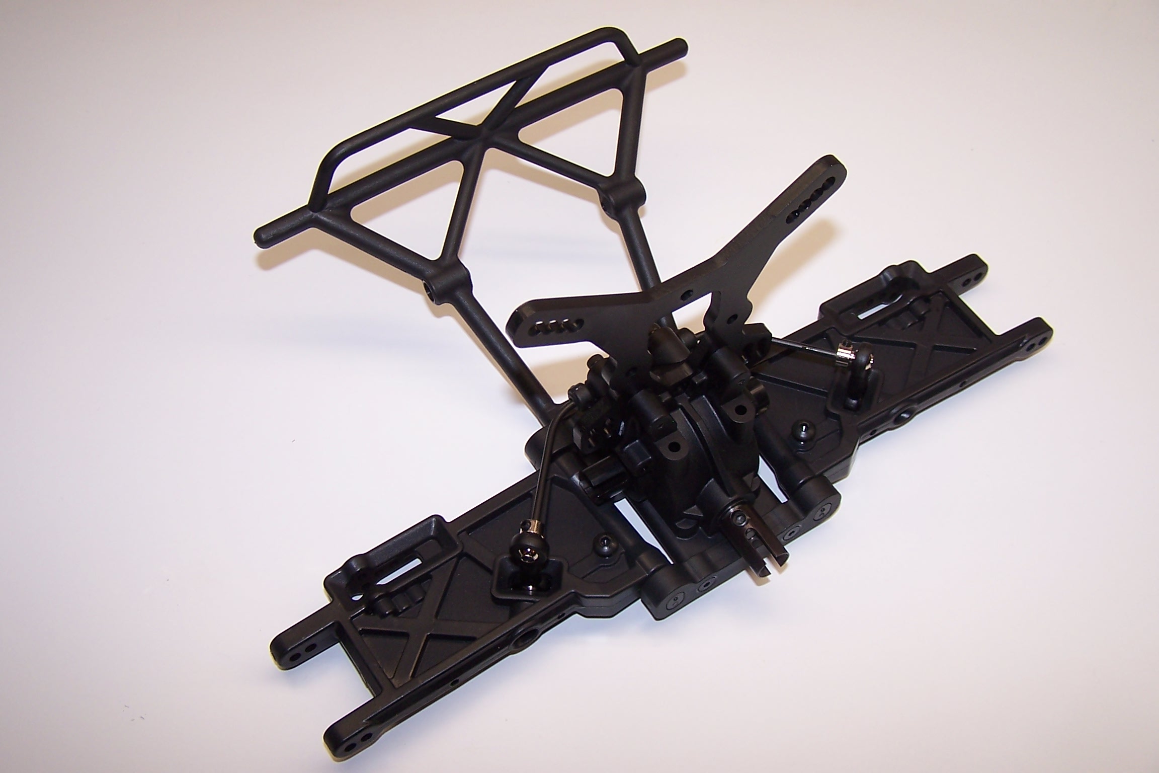
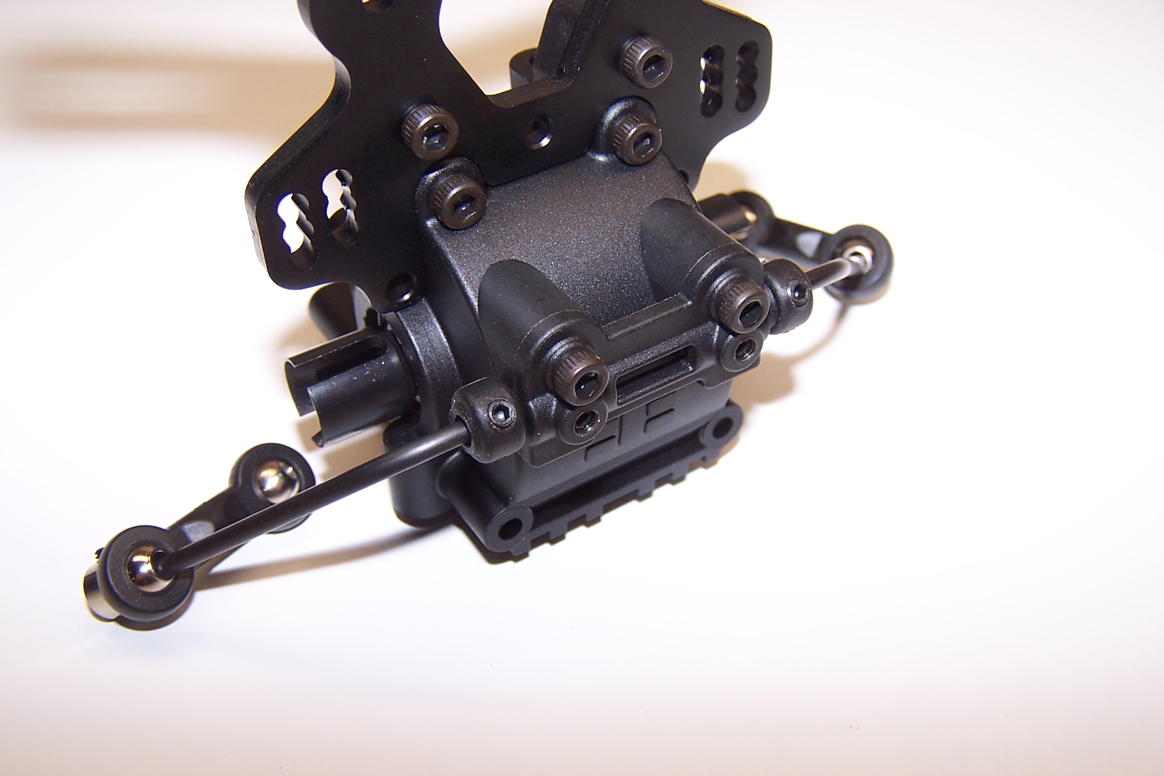
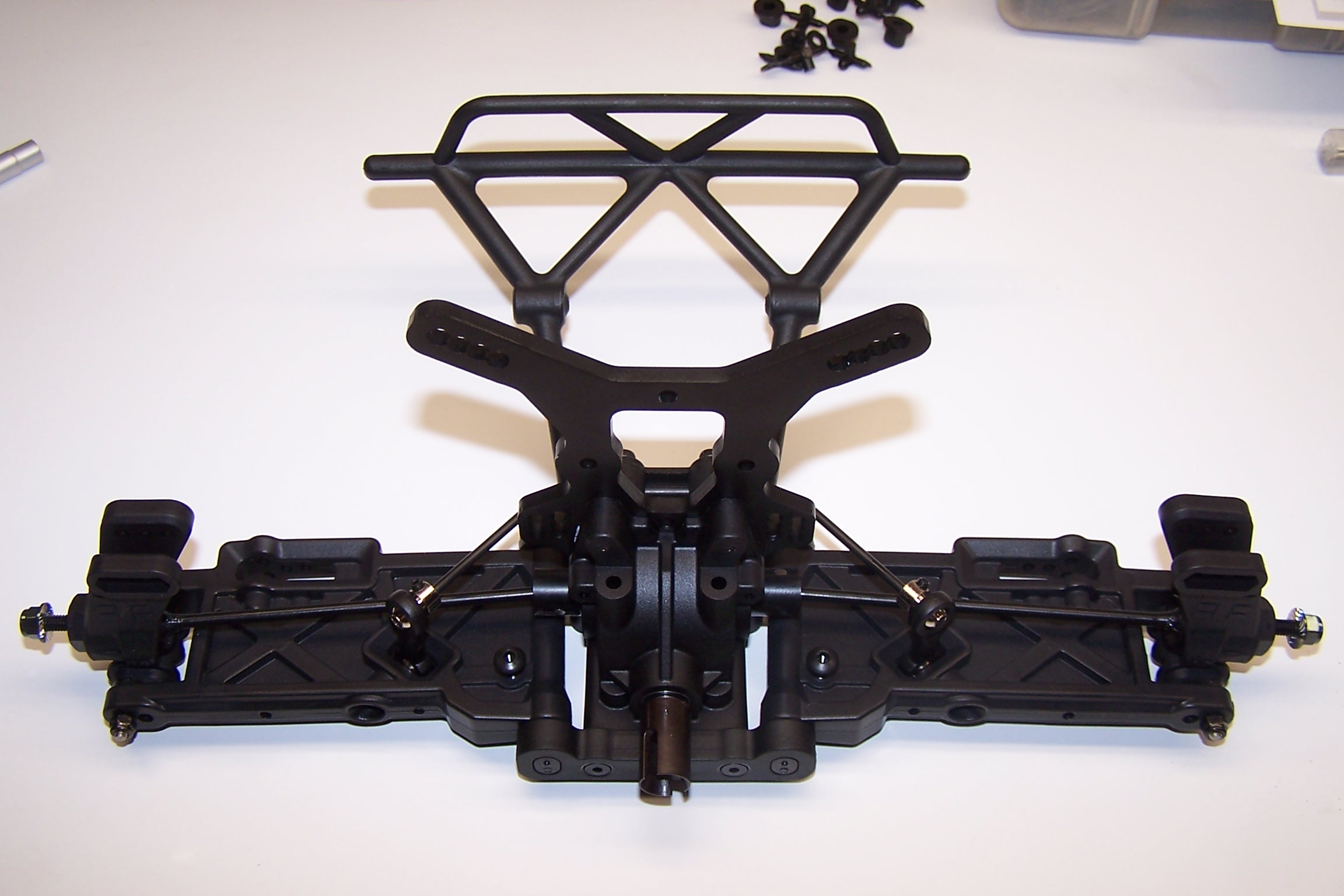
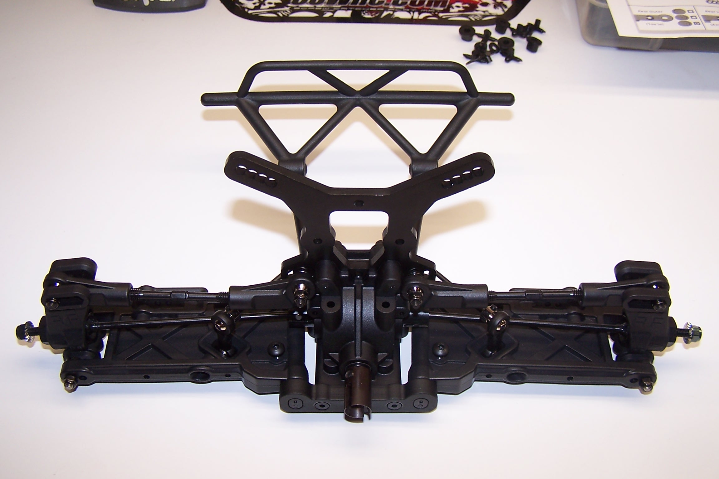
The diff/tower assembly is added to the arms and bumper. Make sure the arms and sway bars do not bind throughout their travel.
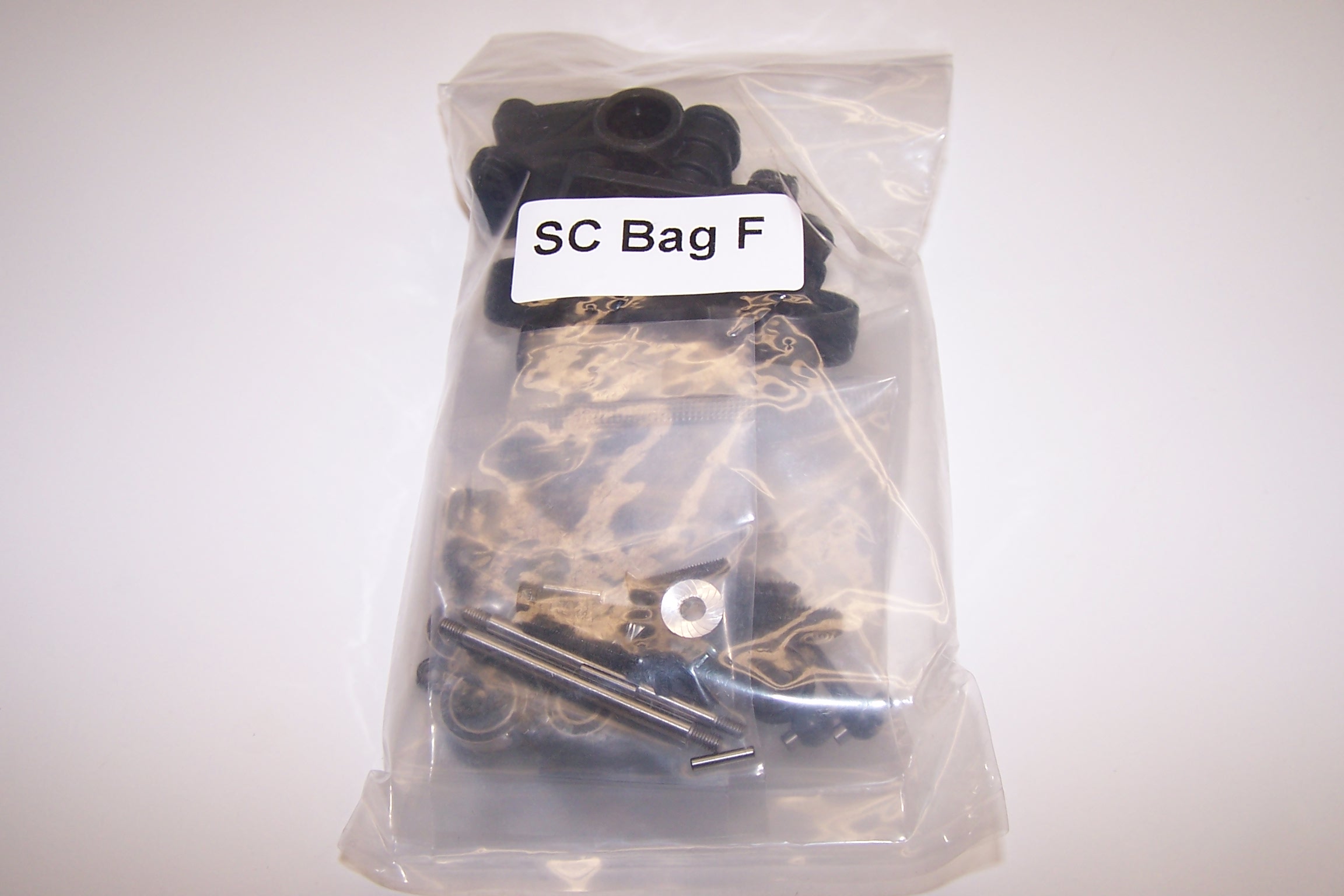
Bag F is a mixed bag. It includes the rest of the bumper pieces, uprights, outdrives, and camber links.
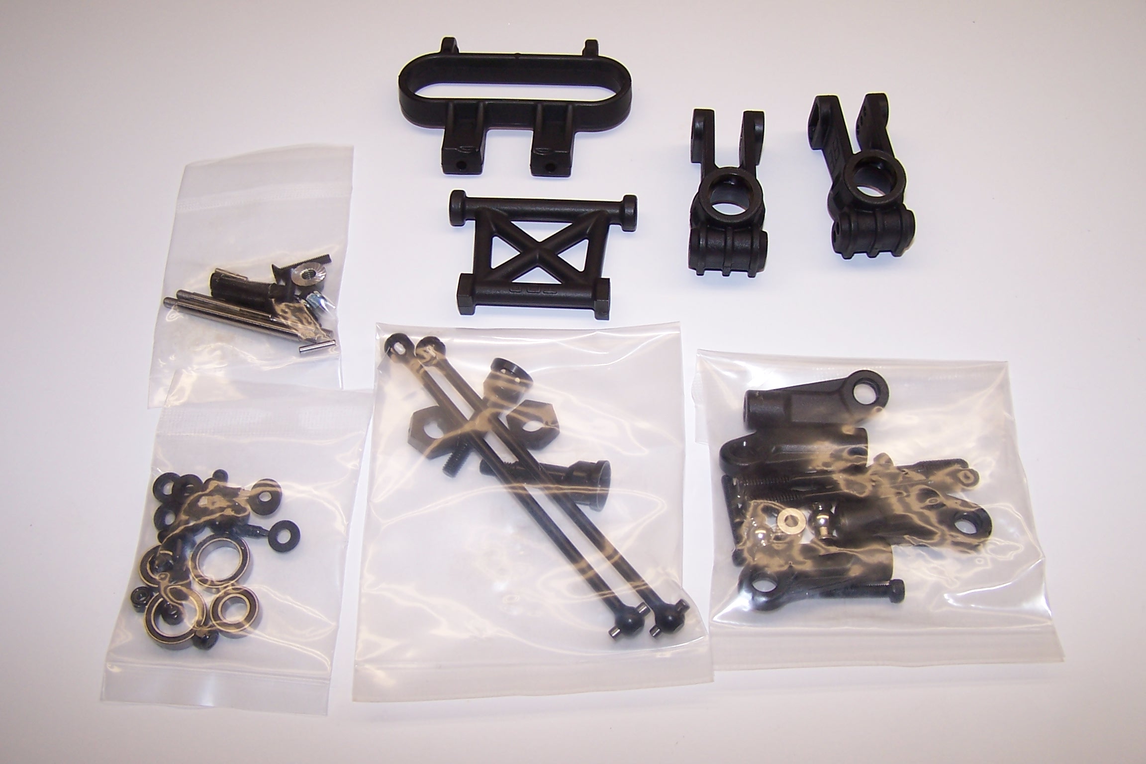
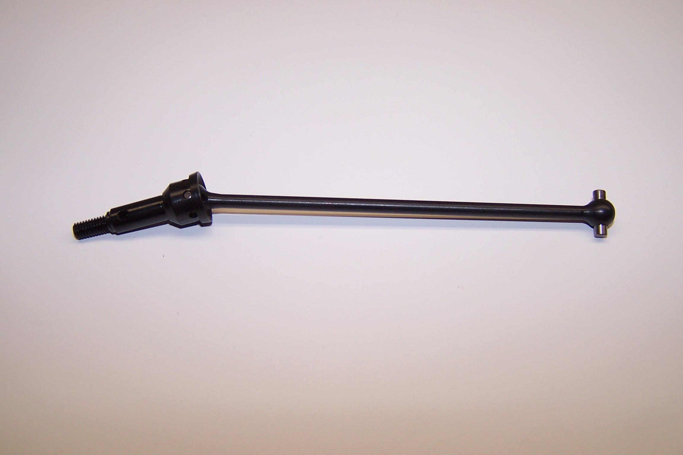
The CVDs go together pretty easily. Make sure you use plenty of thread locking compound on the set screw. You do not want these coming apart and ruining a race.
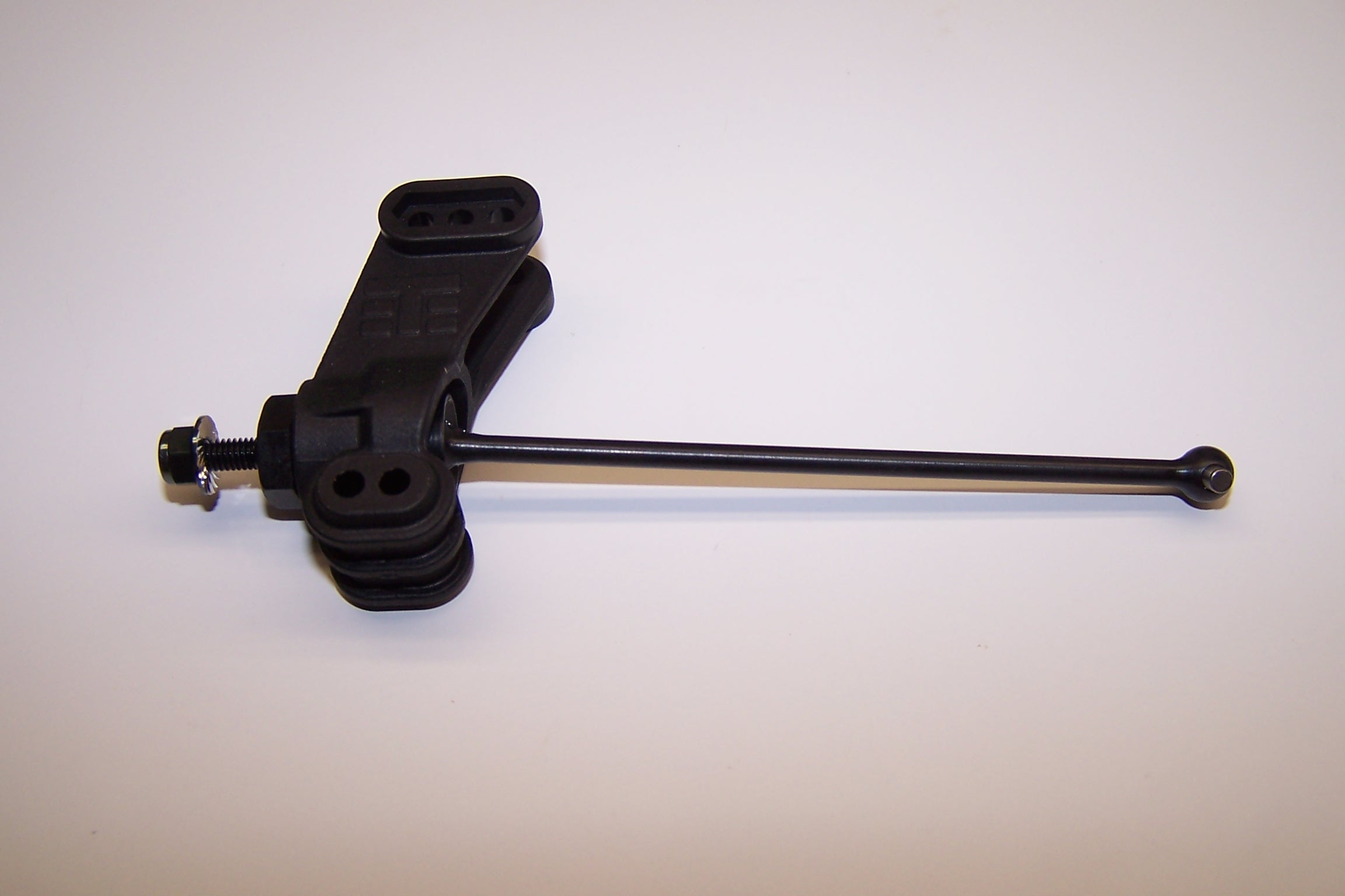
Insert the bearing over the shaft and insert them into the uprights.
Add the CVD assemblies to the rear arms. I set them up on the outside holes per the instructions.
Camber links are assembled and added. Make sure the lines on the camber links are always on the same side. That way you only turn the links one way no matter what side you are on. One thing different from the instructions is to put the camber link screw on in reverse. Put the nut towards the front of the truck. That allows you to access it when the bumper assembly is on.
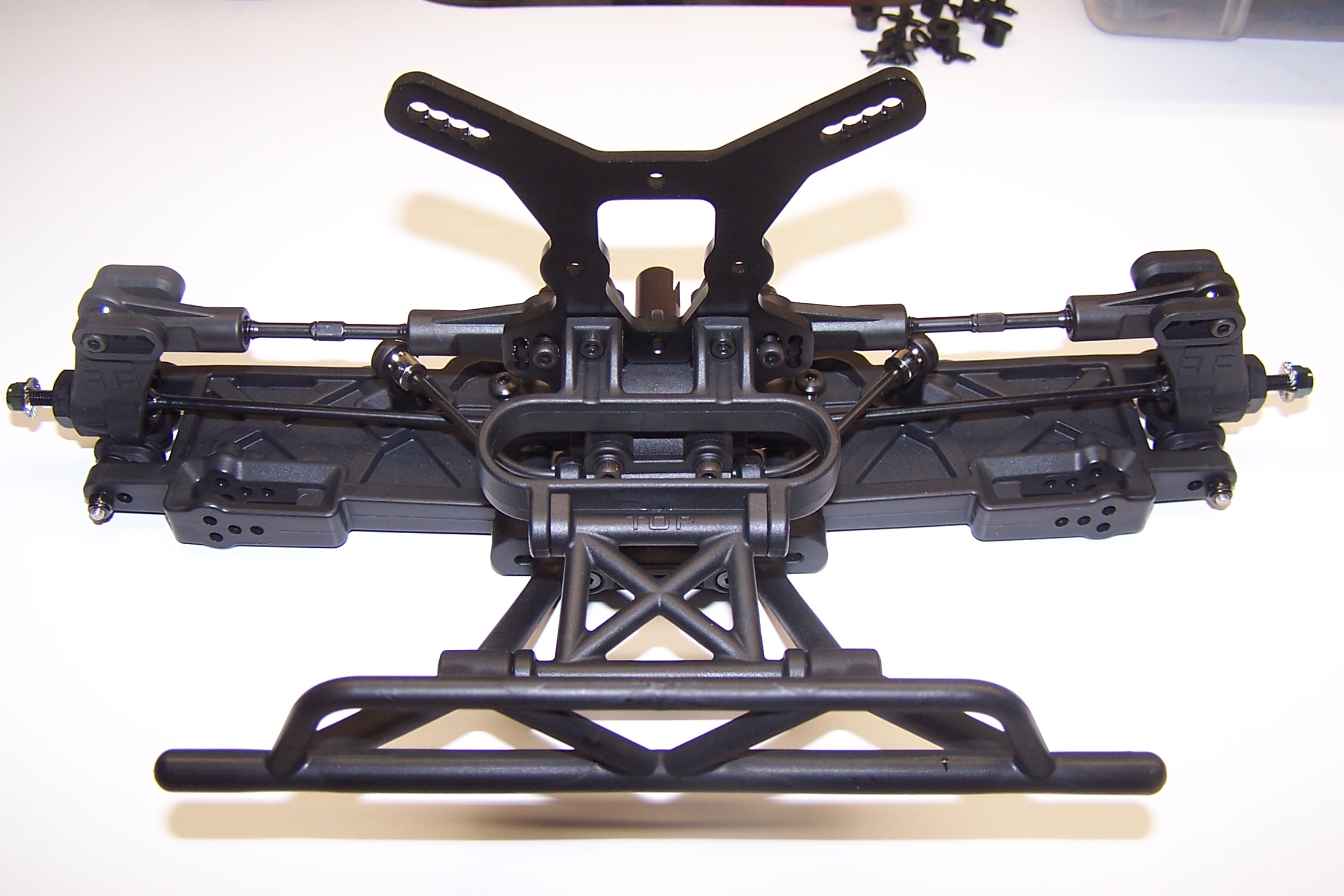
A couple more pieces complete the rear bumper assembly. Some pro drivers do not run the rear bumper assembly. With as rough as the 4×4 Short Course class can get, I’m going to go ahead and leave that on.
 Posted in
  Tags:
Tags: