

 May 23rd, 2013
  Kevin
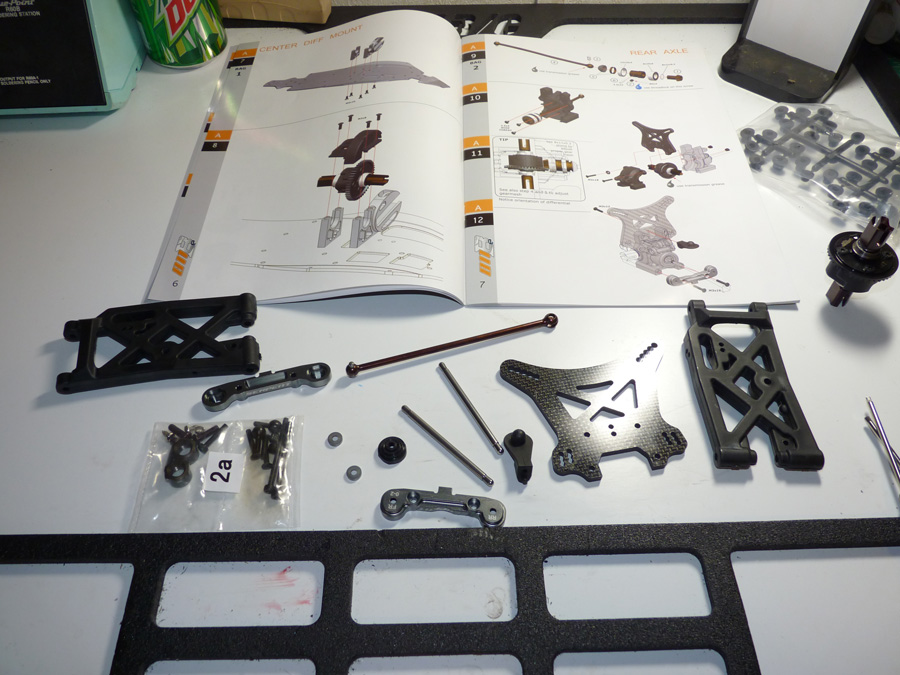
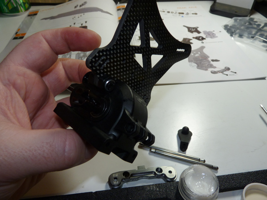
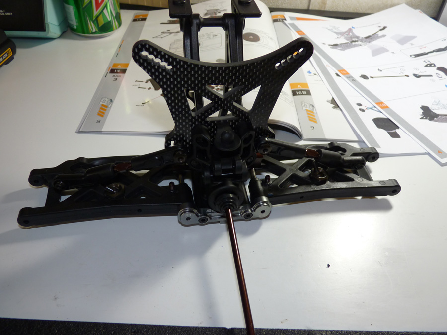
Kevin Now it’s time to build the rest of the rear end. This includes the suspension arms, shock tower, drive train, etc. Here we have the rear suspension bag. The arms are super beefy. The shock tower is thick carbon fiber. It even has aluminum hinge pin holders with adjustable anti-squat inserts.
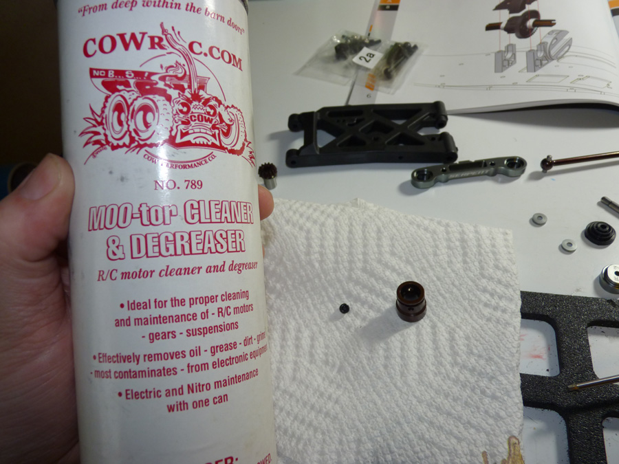
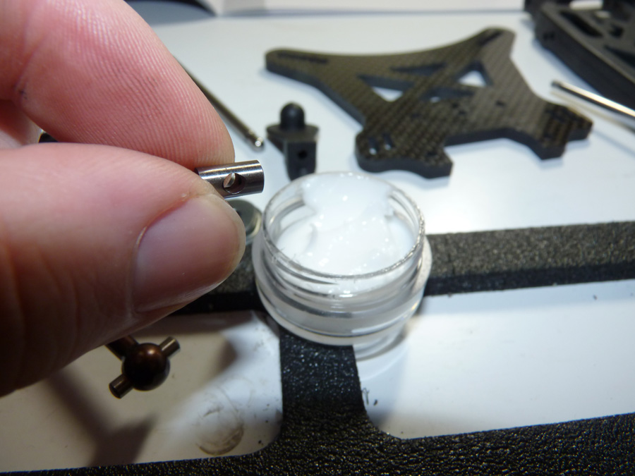
The first thing we need to do is complete that rear diff assembly and install it into the diff case. Per some tips I received, we’re going to clean off the center CV coupler and set screw with CowRC‘s MOO-tor cleaner. This will remove any machining oil left over.
Then we use RED, yes, RED threadlocker on the set screw to secure it and hope it never comes out. The center shaft is one of the fastest spinning parts on the car, and considering this screw is all that secures the pinion gear to the coupler, we do not want it coming off.
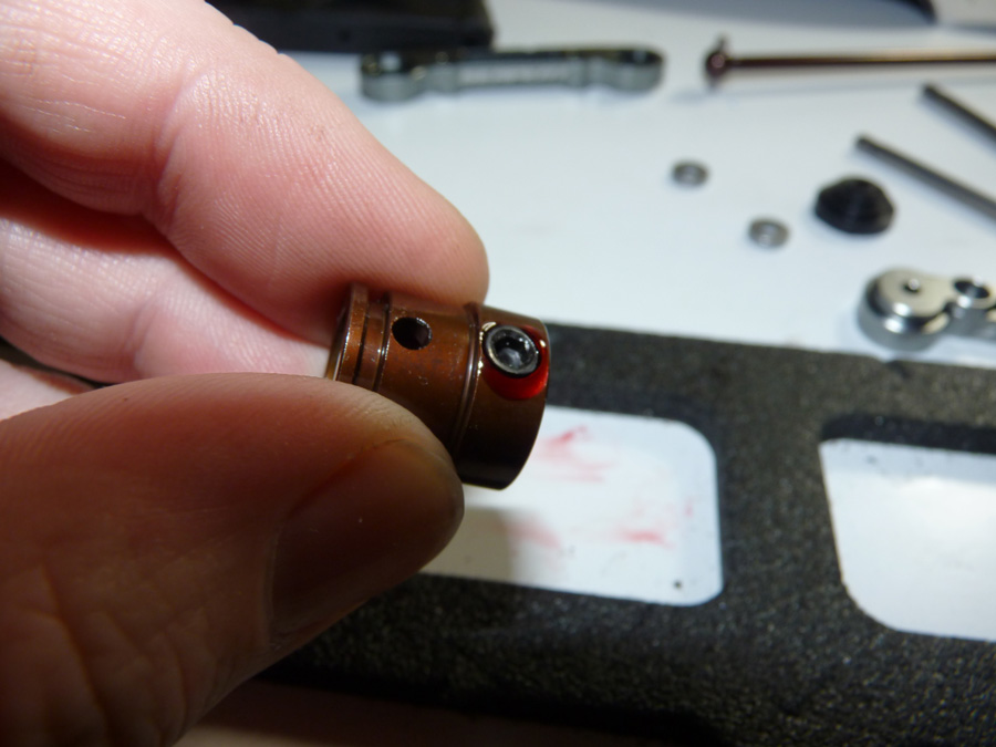
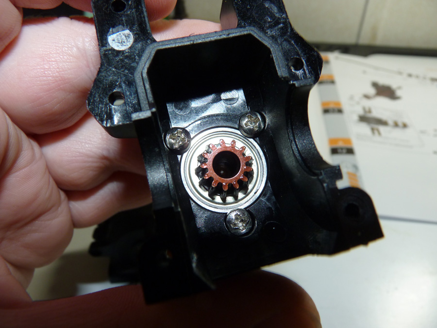
Here is the coupler secured to the pinion shaft with bearing and shim installed.
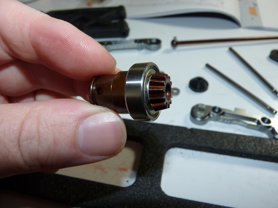
Next we finish the CV assembly.
Here it is assembled.
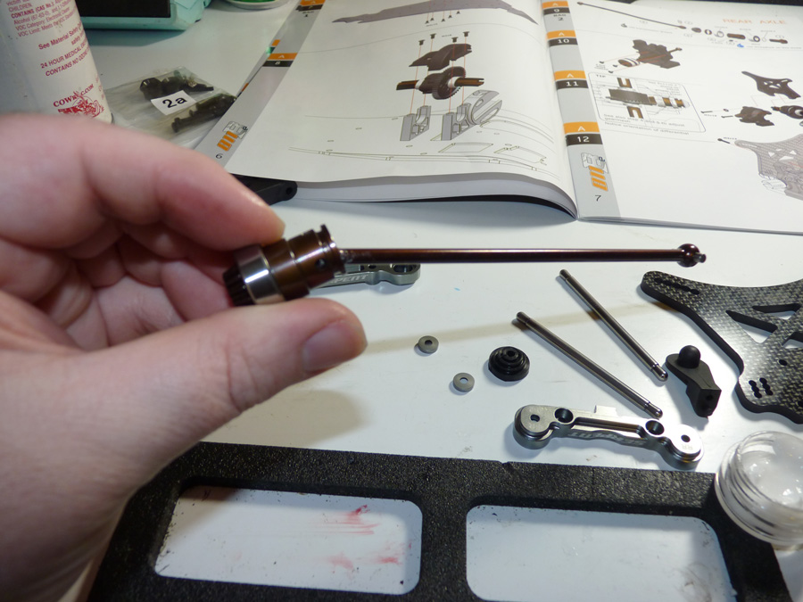
Don’t forget the rubber boot. It will help keep dirt and debris from getting into the CV joint and causing premature wear.
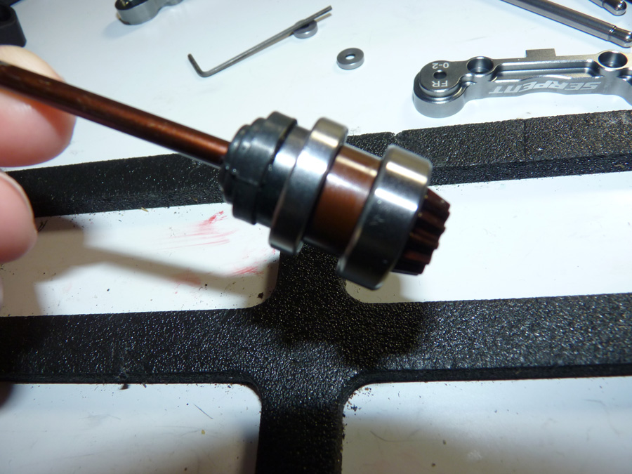
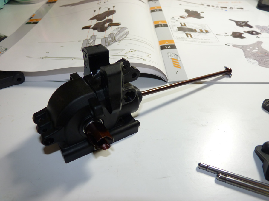
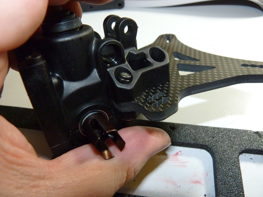
We then slide the center CV assembly thru the diff case.
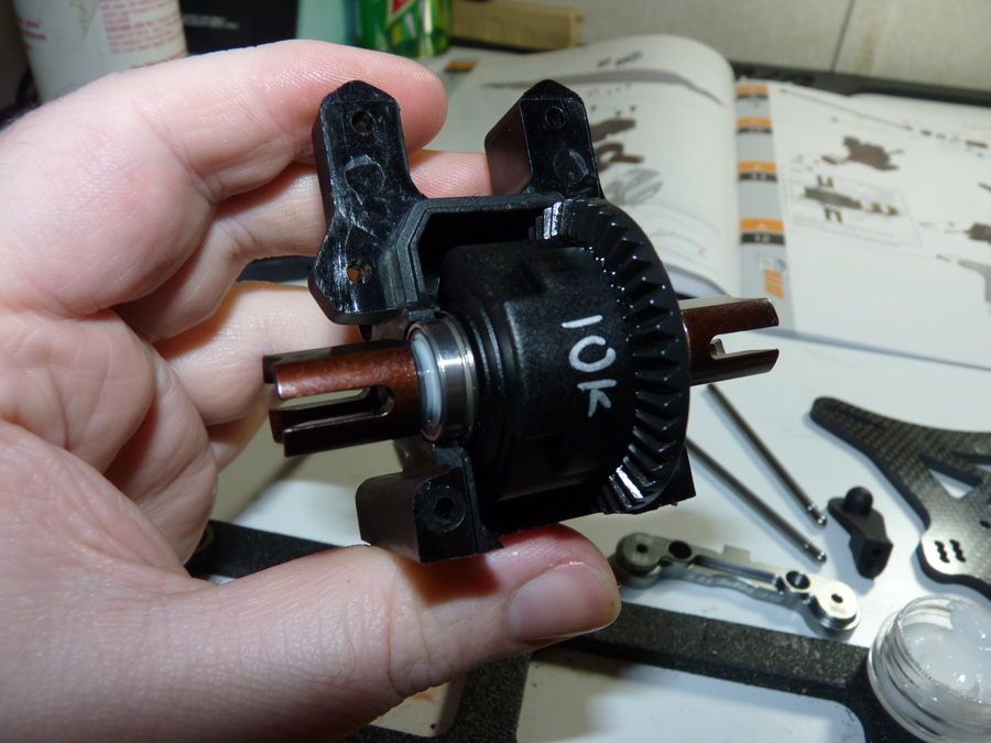
Now would be a good time to double check your shims and make sure everything still moves freely. Oh, and here’s a tip, grab a silver Sharpie and write on your diff with what it’s filled with. It will prevent guess work later.
I mocked up the case half again just to be sure.
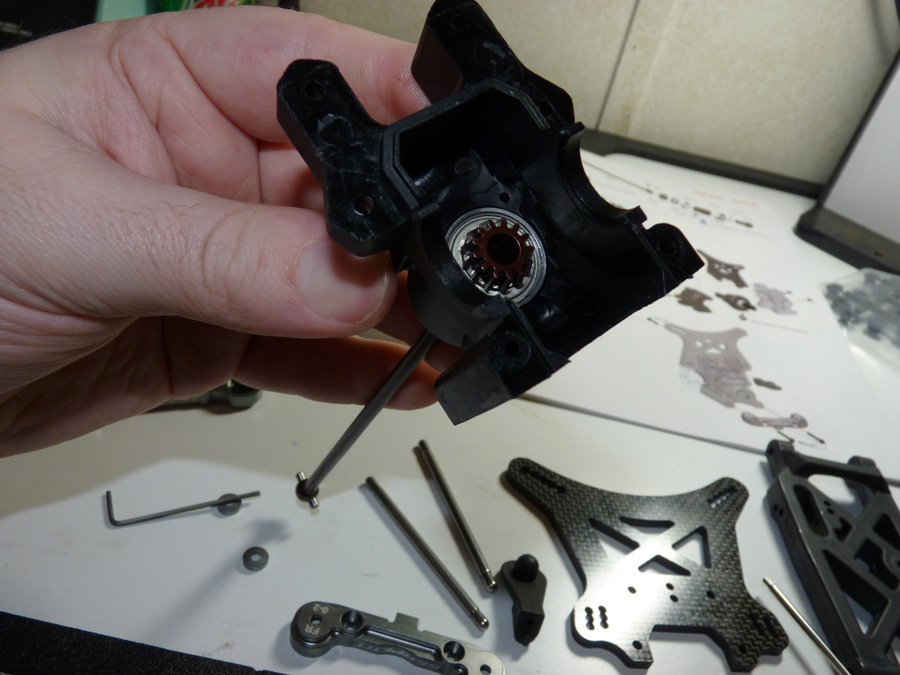
Now here’s something curious.. the Serpent uses these big head phillips screws to secure the bearing into place in the diff case. In the rear I had no issues, but they caused me to take apart the front end of the car about 6 times before I figured out that the ring gear can actually rub the one on it’s respective side! Per one of the team drivers, I removed that screw from the ring gear side in the front and am only using 2 screws. Will go into that again when we do the front.
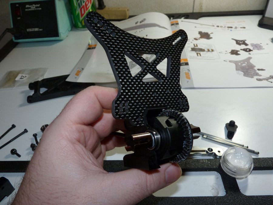
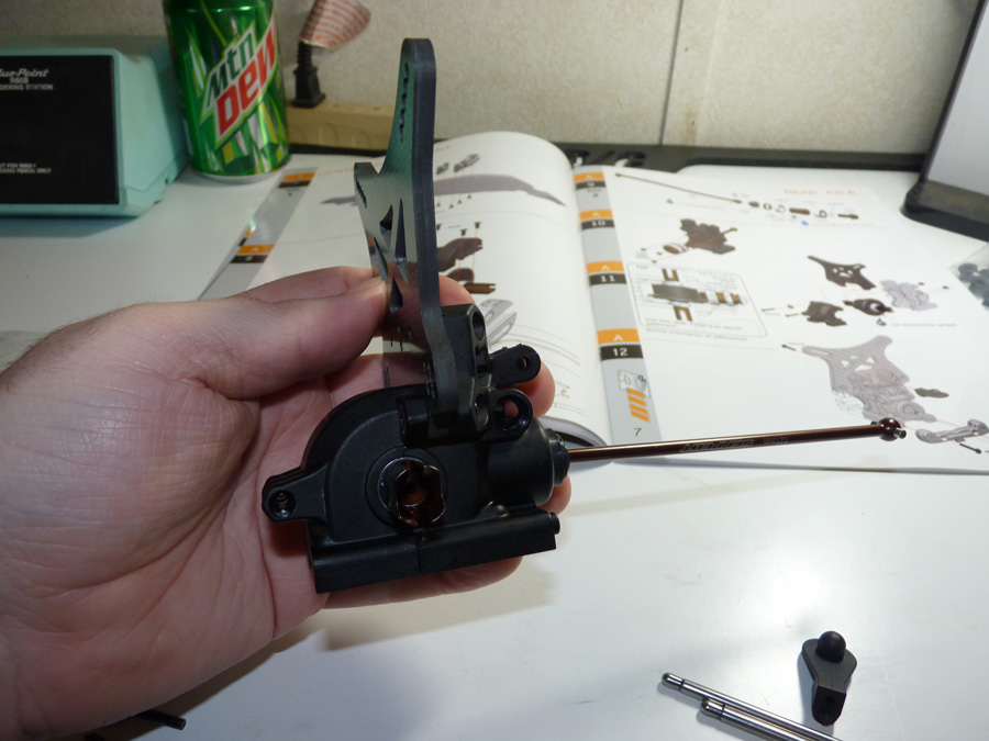
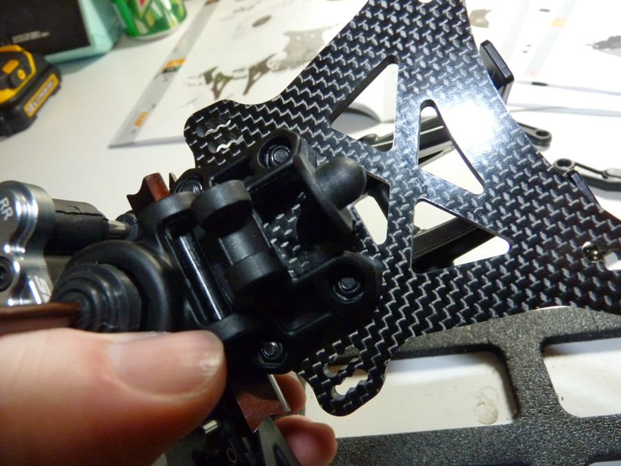
Now we install the rear shock tower, it gets sandwiched between the case halves.
Pretty straight forward here. Just a matter of bolting the 2 case halves together.
The back side of the case has molded in hex areas the hold the locknuts in place and prevent them from spinning, allowing easy tightening. The tolerances are pretty tight, I had to push the locknuts into the recess with some force.
Fit is nice though.
Now we install the rear body mount post to the shock tower.
The hinge pin retainers are next. They are machined aluminum and have a nice silver finish. They are marked as to which is which.
RR on the left designates it’s for the Rear, and the FR on the right assigns it to the front of the rear diff case.
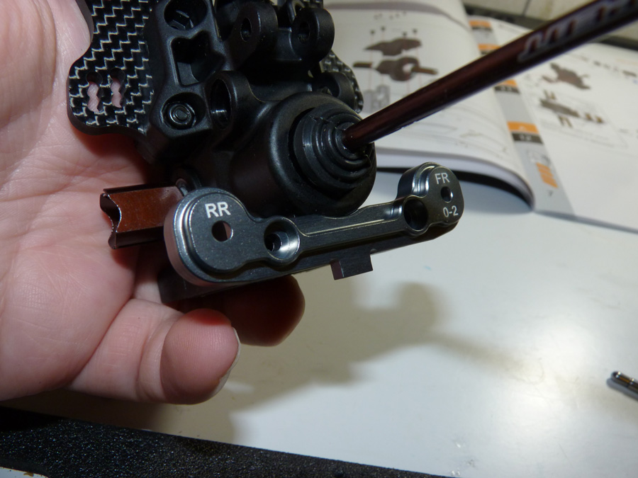
2 bolts into the case and it’s attached.
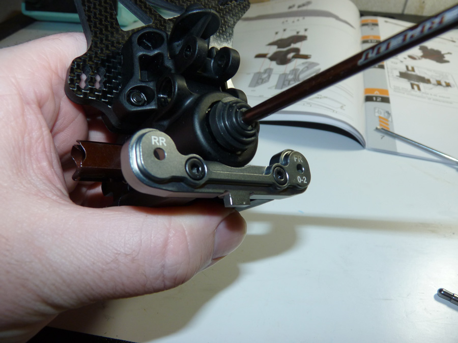
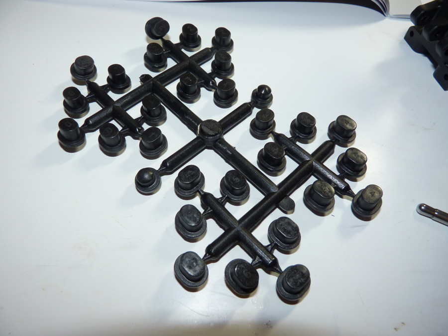
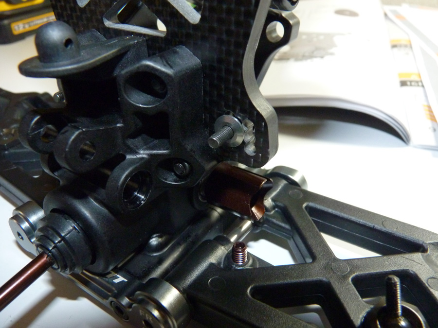
Here are those adapters I was referring to earlier. They look like little top hats and remind me of the rear ride height adjustment slugs in pan cars. They are numbered so you can keep them straight. Refer to whatever setup sheet you are using as to which you need, and pay attention to orientation, because like ride height slugs, they can be inserted upside down.
Plug slot on the hinge pin holder.
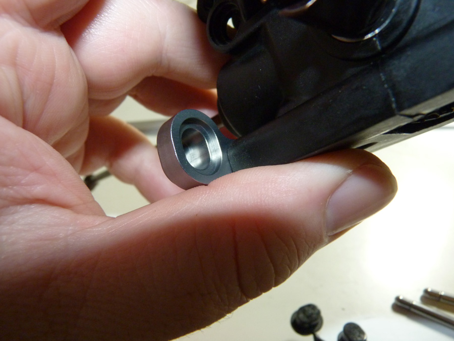
And now with them inserted. The fit is perfect.
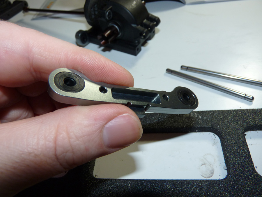
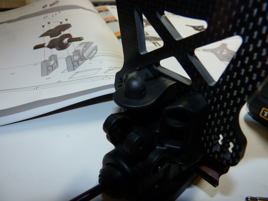
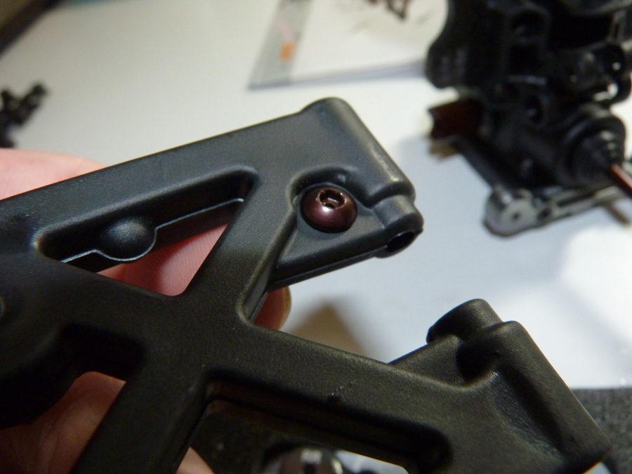
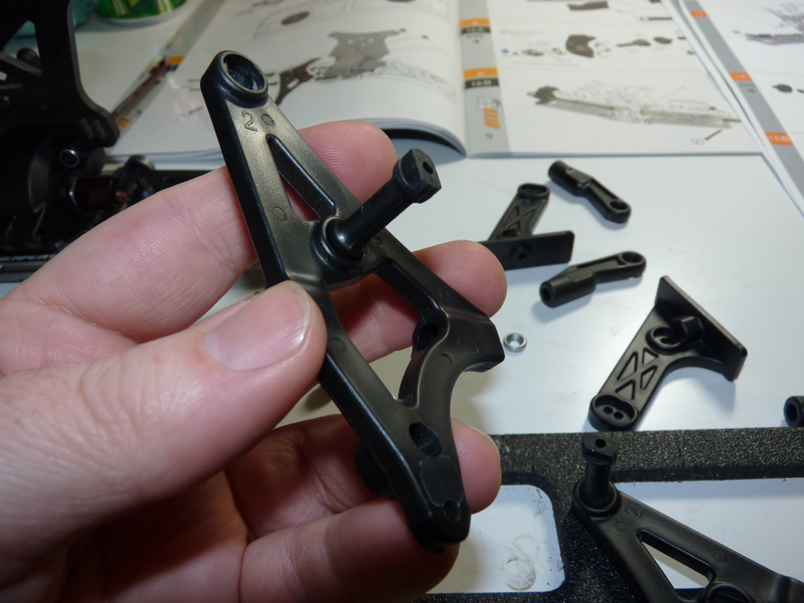
The next part was a bit unusual for me (though I’m not that familiar with 1/8 racing to know if this is a common feature). The arms have a molded in spot for a pivot ball for the sway bars.
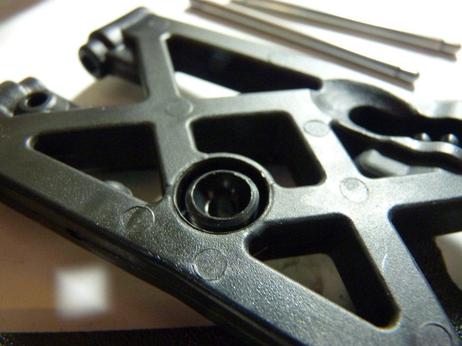
Simply insert the ball into the hole. I put a thin layer of grease on mine to smooth out the pivot action.
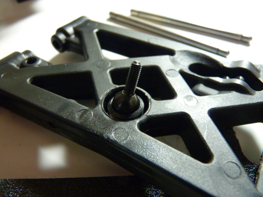
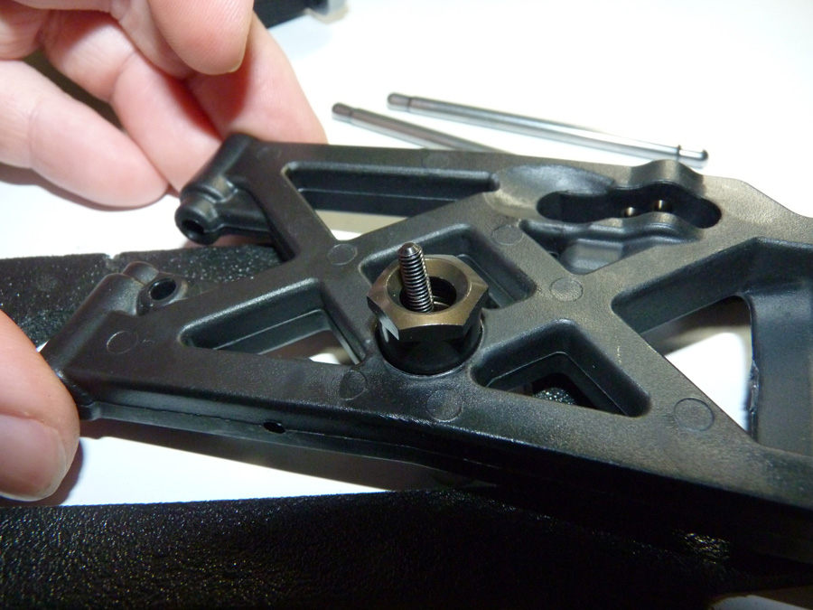
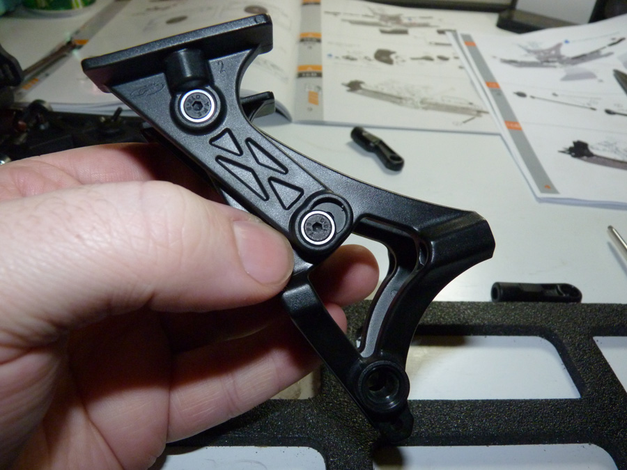
Then a cap is installed over it, that threads down into the arm to hold it in place. Make sure you install this square as to not destroy the threads on the arm. Also be sure not to overtighten it.
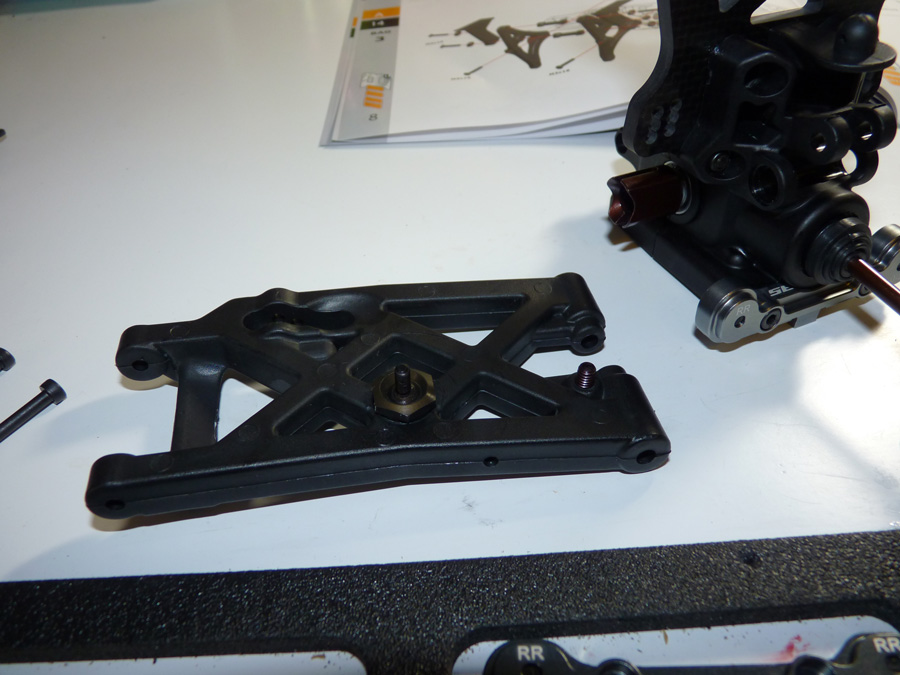
Next we install the droop screws. These can be adjusted from either end and allow you to set the down travel (droop) of the suspension.
Here we have a prepped suspension arm.
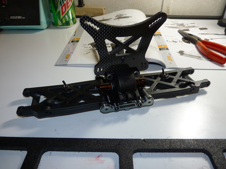
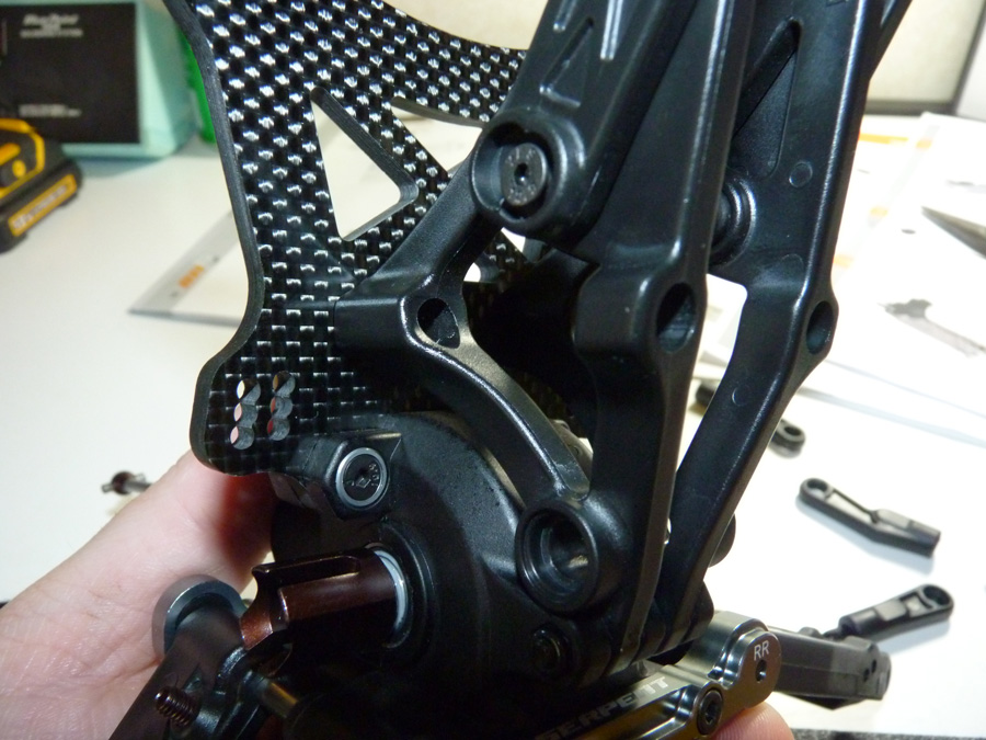
Next we put the hinge pins in the arms, and attach the other holder on the back of the diff case to secure them. The arms are now attached to the rear end.
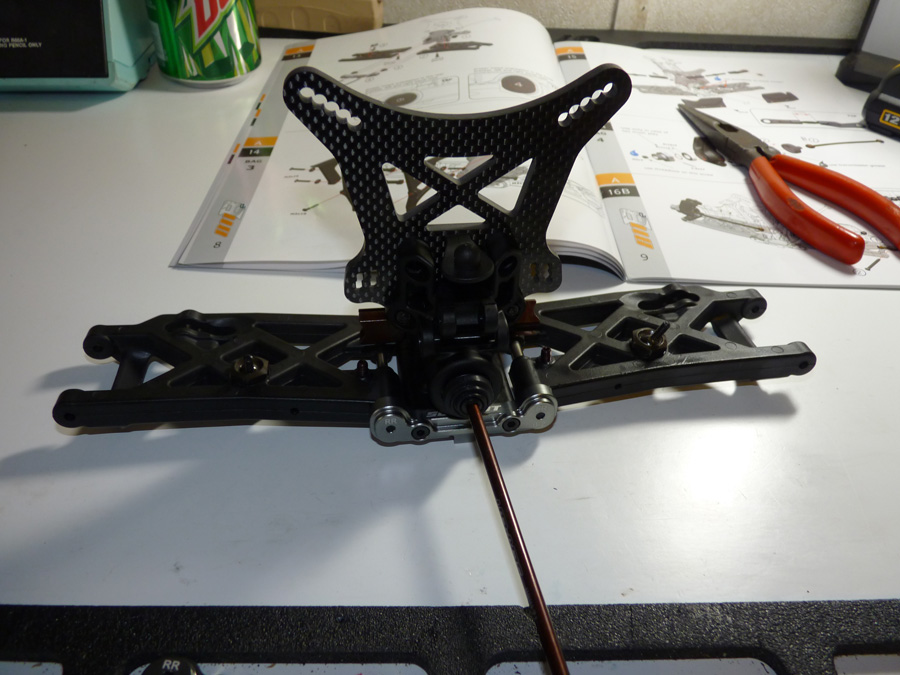
Here’s a view of the other side.
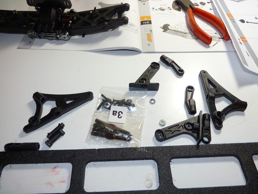
Next we have the wing mount and the rear camber links. Below are the parts we’ll use to complete those.
We’ll first install the cross members in the wing mount. It bummed me out a little that these were plastic, but they should work fine.
There are 2 adjustment holes on the lower part of the mount to adjust the pitch of the wing.
The lower part is attached to the diff housing with a long through-screw and locknut.
The upper part secures to the shock tower/diff half.
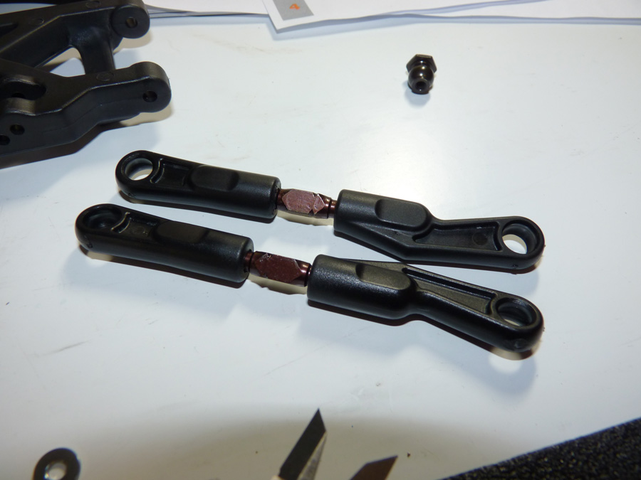
We then assemble the rear camber links. There is no 1:1 diagram for these like I love in most manuals, but they provide a rough measurement to follow that you can measure with a set of calipers.
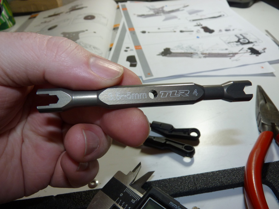
My new favorite tool in assembling turnbuckles is this little TLR wrench. It seems to fit almost every car I own and is much nicer on the turnbuckles than a set of needle-nose pliers.
Now we’ll get ready to mount up the camber links.
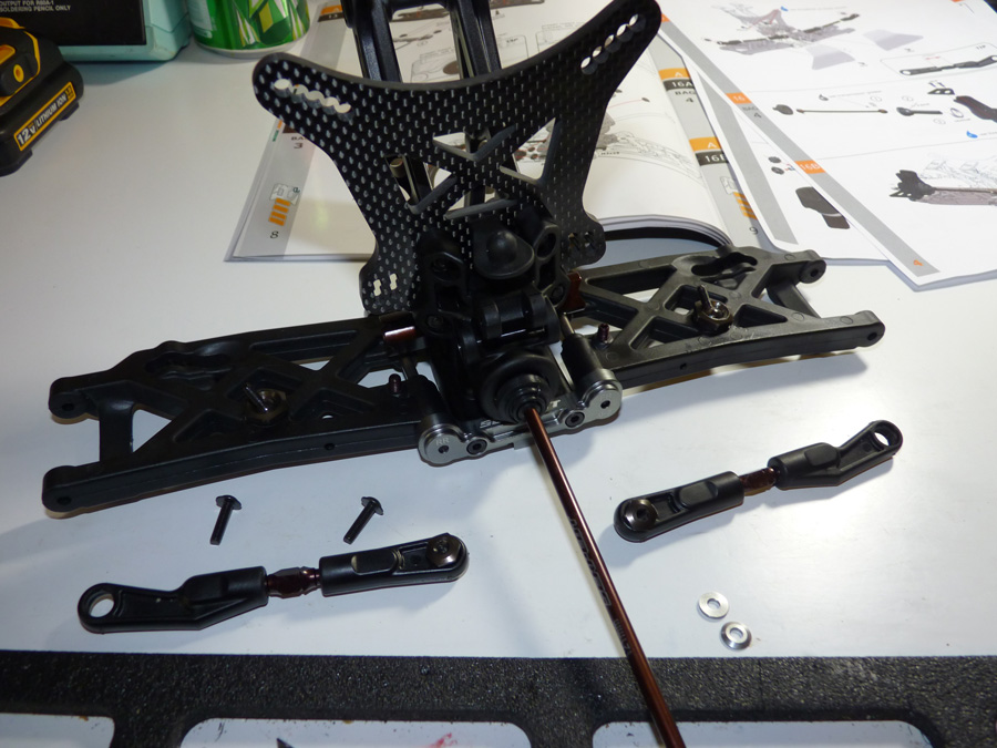
This requires a long screw, with a conical washer.
Serpent uses this unique threaded ball/nut to secure the link. Make sure to use threadlock here!
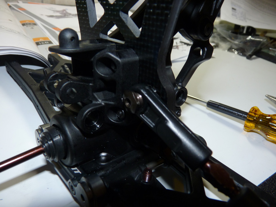
Now we have camber links!
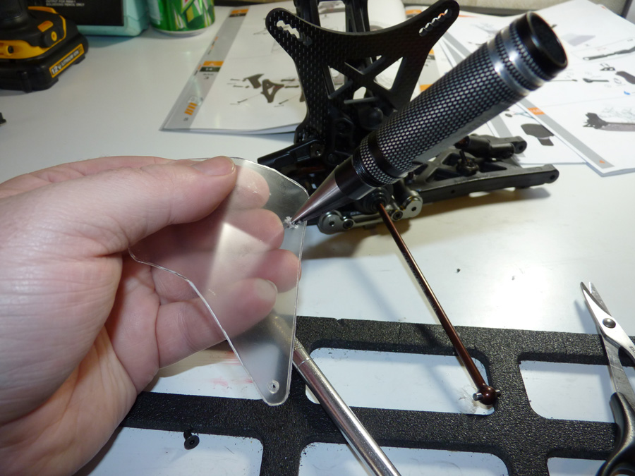
Next up, rear mud guards. These are formed from pretty thick lexan. You could probably paint them if you wanted, but I figured it would look best left clear. Simply cut them out with decent curved lexan scissors.
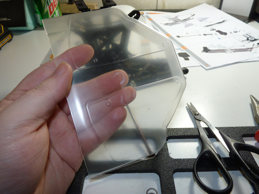
I used my trusty reamer to punch holes in the marked locations where they mount to the arms.
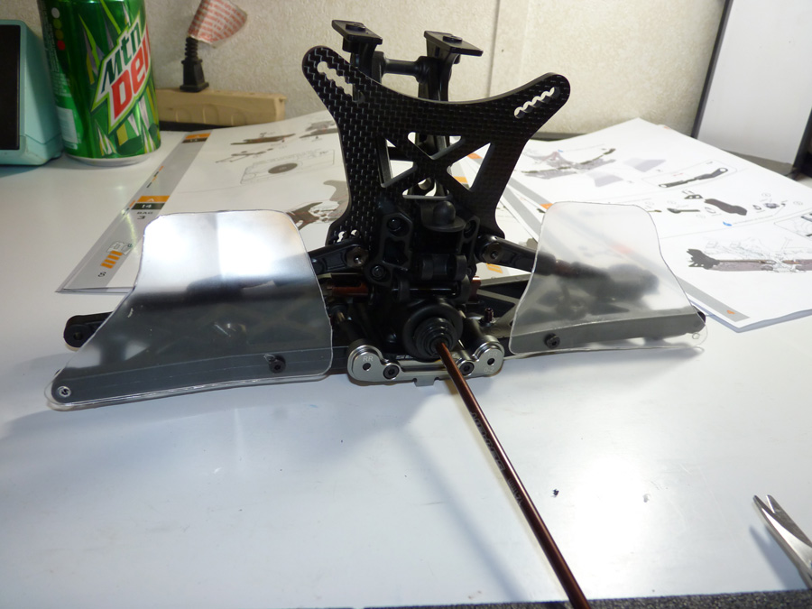
They screw in with one screw each, the outer ends will be secured with the hinge pins.
 Posted in
  Tags:
Tags: